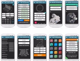
CNC machining drawing in is a crucial aspect of modern manufacturing, bridging the gap between design and production. Understanding this process allows engineers and designers to create precise, efficient, and functional components. As industries increasingly rely on automation, mastering CNC drawing techniques becomes essential for staying competitive.
In this guide, readers will explore the fundamentals of CNC machining drawing, including essential tools, software, and best practices. We will delve into the intricacies of creating accurate technical drawings, interpreting specifications, and ensuring quality control. By the end, readers will be equipped with the knowledge to enhance their CNC machining skills and improve their production workflows.
How to Prepare a Technical Drawing for CNC Machining
Technical drawings are widely used in manufacturing to improve the communication of technical requirements between the designer, engineer, and manufacturer. They serve as a crucial bridge between the conceptual design and the physical part, ensuring that all specifications are met during the CNC machining process. This guide will delve into the essential aspects of preparing technical drawings for CNC machining, highlighting their importance, key features, and the differences between various types of drawings.
Importance of Technical Drawings in CNC Machining
Technical drawings play a vital role in the CNC machining process. They provide detailed information that a 3D CAD file alone may not convey, such as tolerances, surface finishes, and specific features like threads. These drawings ensure that all parties involved in the manufacturing process have a clear understanding of the part’s requirements, which helps to minimize errors and improve efficiency.
Key Technical Features of CNC Machining Drawings
Understanding the essential components of CNC machining drawings is crucial for effective communication and manufacturing. Below is a comparison table of the key technical features commonly found in these drawings:
| Feature | Description |
|---|---|
| Title Block | Contains basic information about the part, including part name, material, and scale. |
| Orthographic Views | 2D representations of the part from different angles, conveying dimensions and features. |
| Isometric View | A 3D representation that provides a clearer understanding of the part’s geometry. |
| Section Views | Show internal features of the part, indicating where the part has been cut. |
| Detail Views | Highlight complex areas of the part for better clarity and understanding. |
| Dimensions | Specify the size and location of features, ensuring accuracy in manufacturing. |
| Tolerances | Indicate acceptable variations in dimensions, crucial for part functionality. |
| Notes to Manufacturer | Additional instructions that provide context and specific requirements for the machining process. |
Types of CNC Machining Drawings
Different types of CNC machining drawings serve various purposes in the manufacturing process. Below is a comparison table highlighting the differences between these types:
| Type | Description |
|---|---|
| Engineering Drawings | Detailed drawings that include all specifications necessary for manufacturing. |
| Assembly Drawings | Show how different parts fit together, often including exploded views. |
| Detail Drawings | Focus on specific components, providing intricate details and dimensions. |
| Fabrication Drawings | Used for manufacturing processes, detailing how parts should be made. |
| Shop Drawings | Created by contractors, showing how the design will be constructed on-site. |
Preparing Technical Drawings for CNC Machining
When preparing technical drawings for CNC machining, follow these steps to ensure clarity and accuracy:
-
Define Critical Views: Start by identifying the most important views of the part and position the relevant orthographic views centrally on the drawing.
-
Add Section and Detail Views: If the part has complex internal features, include section views to provide a clearer understanding of its structure.
-
Include Construction Lines: Use construction lines to indicate symmetry and center points, aiding in the accurate placement of dimensions.
-
Dimensioning: Add dimensions to the drawing, focusing on critical features first. Ensure that dimension lines do not overlap or clutter the drawing.
-
Specify Threads and Holes: Clearly indicate the size, location, and length of all threads and holes, using callouts where necessary to simplify the drawing.
-
Add Tolerances: Include tolerances for features that require higher accuracy than standard practices, ensuring that the part meets functional requirements.
-
Fill in the Title Block: Ensure that all relevant information, including material specifications and surface finish requirements, is included in the title block.
-
Export the Drawing: Once completed, export the drawing as a PDF file for easy sharing and reference during the manufacturing process.
Conclusion
Technical drawings are an essential part of the CNC machining process, providing the necessary details to ensure that parts are manufactured accurately and efficiently. By understanding the key features and types of drawings, as well as following best practices for preparation, designers and engineers can facilitate better communication with machinists and improve the overall quality of the final product. Websites like www.hubs.com, chansmachining.com, at-machining.com, xometry.pro, and proleantech.com offer valuable resources and insights into the world of CNC machining and technical drawing preparation.
FAQs
Related Video
Watch a video about “cnc machining drawing”
What is the purpose of a title block in a technical drawing?
The title block contains essential information about the part, including the part name, material, scale, and the names of individuals involved in the design and approval process.
Why are tolerances important in CNC machining drawings?
Tolerances specify the acceptable range of variation for dimensions, ensuring that parts fit together correctly and function as intended.
What types of views are typically included in CNC machining drawings?
Common views include orthographic views, isometric views, section views, and detail views, each providing different perspectives and information about the part.
How do I ensure my technical drawing is clear and easy to understand?
Use standard symbols, avoid excessive hidden lines, and ensure that dimensions are clearly marked and do not overlap to enhance clarity.
Can I rely solely on a 3D CAD model for CNC machining?
While a 3D CAD model contains crucial information, accompanying it with a technical drawing is recommended to provide additional details and ensure clear communication with machinists.