Contents
Manufacturing Insight: Cnc Cut Files
Manufacturing Insight: CNC Cut Files
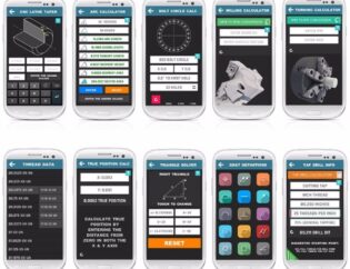
CNC cut files represent the critical translation of digital designs into executable machining instructions, forming the backbone of precision manufacturing. At Shenzhen Honyo Prototype, we define these files as validated G-code or machine-specific toolpaths generated through Computer-Aided Manufacturing (CAM) software. Unlike raw CAD models, CNC cut files encapsulate tool selection, cutting sequences, feed rates, spindle speeds, and collision-avoidance logic—transforming geometric data into actionable physical operations. This conversion ensures dimensional accuracy, surface finish consistency, and material integrity, directly impacting part functionality and assembly compatibility.
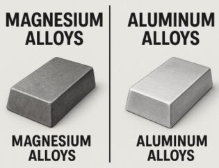
The integrity of CNC cut files hinges on rigorous preprocessing. Honyo’s engineering team conducts comprehensive Design for Manufacturability (DFM) analysis to identify potential flaws such as inadequate tool access, suboptimal wall thicknesses, or unachievable tolerances. We validate file compatibility across our multi-axis CNC platforms (3-axis, 4-axis, and 5-axis), ensuring seamless integration with machine controllers. Our process eliminates common pitfalls like over-travel errors or inefficient toolpath sequencing, which can cause scrap rates to exceed 15% in unverified workflows. Material behavior is equally critical; aluminum alloys demand different chip-load strategies than engineering plastics like PEEK, necessitating file parameter adjustments to prevent burring or thermal deformation.
Honyo leverages 15+ years of prototyping expertise to optimize CNC cut files for speed without sacrificing precision. Our in-house CAM specialists fine-tune toolpaths for complex geometries—such as undercuts or thin-walled features—using adaptive clearing techniques that reduce cycle times by 20–30% versus standard approaches. All files undergo multi-stage verification: virtual machine simulation checks for collisions, followed by first-article inspection against AS9102 standards. This reduces setup iterations and accelerates time-to-prototype, particularly for low-volume, high-mix production common in aerospace and medical sectors.
Below are key specifications reflecting our CNC machining capabilities:
| Parameter | Standard Tolerance | Tight Tolerance Option |
|——————–|——————–|————————|
| Dimensional | ±0.05 mm | ±0.005 mm |
| Hole Diameter | ±0.025 mm | ±0.005 mm |
| Surface Roughness | Ra 1.6 μm | Ra 0.4 μm |
| Flatness | 0.05 mm/m | 0.01 mm/m |
| Material Category | Examples | Max Part Size (mm) |
|——————–|———————————–|——————–|
| Metals | 6061-T6, 7075-T6, SS304, Titanium | 1200 × 600 × 500 |
| Engineering Plastics | PEEK, Delrin, Nylon, PTFE | 1000 × 500 × 400 |
| Composites | G10, FR4, Carbon Fiber Reinforced | 800 × 400 × 300 |
Shenzhen Honyo Prototype delivers more than file processing—we provide engineered solutions. Our integrated workflow, from file validation to post-machining deburring, ensures prototypes and end-use parts meet stringent functional requirements. By prioritizing file optimization and material science alignment, we achieve 99.2% first-pass yield across 500+ annual projects. Partner with Honyo for CNC cut files that transform digital intent into physical excellence, backed by ISO 9001-certified processes and responsive technical collaboration.
Technical Capabilities
CNC Machining Technical Capabilities at Shenzhen Honyo Prototype
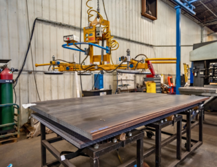
Shenzhen Honyo Prototype delivers precision CNC machining services tailored for rapid prototyping and low-to-mid volume production. Our advanced 3-axis, 4-axis, and 5-axis milling centers, combined with high-precision CNC turning systems, enable us to produce complex geometries with exceptional accuracy and surface finish. We specialize in tight-tolerance components across a wide range of engineering materials, serving industries such as aerospace, medical devices, automotive, and industrial equipment.
Our 3-axis milling capabilities are ideal for prismatic parts with straightforward geometries, offering fast turnaround and cost-effective solutions. For components requiring multi-sided machining or undercuts, our 4-axis CNC machines provide rotational indexing around the A-axis, enabling efficient machining of cylindrical contours and angled features. For the most complex 3D surfaces—such as impellers, turbine blades, or ergonomic housings—our 5-axis simultaneous milling systems deliver superior precision with reduced setup times, minimizing human error and ensuring geometric consistency.
CNC turning is optimized for cylindrical or near-cylindrical parts, including shafts, bushings, and threaded components. Our live-tooling turning centers support mill-turn operations, allowing us to perform secondary milling, drilling, and tapping in a single setup, which enhances accuracy and part integrity.
Tight-tolerance machining is a core competency. We consistently achieve tolerances down to ±0.005 mm (±0.0002″) on critical dimensions, depending on part geometry, material, and feature size. Our quality assurance process includes first-article inspection (FAI), in-process checks, and final CMM (Coordinate Measuring Machine) reporting, ensuring compliance with ISO 2768 and customer-specific GD&T requirements.
Surface finish is controlled through optimized toolpaths, high-speed spindles (up to 24,000 RPM), and fine-grade cutting tools. Standard surface finishes range from 3.2 µm (125 µin) to 0.8 µm (32 µin) Ra, with the ability to achieve mirror finishes through polishing or specialized tooling upon request.
Below is a summary of our standard tolerance and material capabilities:
| Feature | Typical Tolerance | Material Options |
|——–|——————-|——————|
| Linear Dimensions | ±0.01 mm (±0.0004″) | Aluminum (6061, 7075, 2024), Stainless Steel (303, 304, 316), Steel (1018, 4140), Titanium (Grade 2, 5), Brass (C3604), Plastics (ABS, POM, PC, PEEK, Nylon) |
| Hole Diameter | +0.025 / –0 mm | Aluminum Alloys, Stainless Steel, Plastics |
| Positional Tolerance | ±0.02 mm (±0.0008″) | All machinable metals and engineering plastics |
| Angular Features | ±0.1° | Metals and rigid thermoplastics |
| Surface Finish (Milling) | 3.2–0.8 µm Ra (standard) | All materials; finer finishes available with polishing or special tooling |
| Surface Finish (Turning) | 1.6–0.4 µm Ra (standard) | Metals and plastics with good machinability |
All CNC programs are generated using industry-leading CAM software (Siemens NX, Mastercam, and SolidCAM), ensuring optimal toolpath efficiency and material removal rates. We accept native CAD files (STEP, IGES, X_T, SLDPRT) and detailed 2D drawings with GD&T callouts to ensure full manufacturability and dimensional intent.
From CAD to Part: The Process
CNC Cut Files Production Workflow: From CAD to Finished Part
At Shenzhen Honyo Prototype, our CNC machining process transforms client CAD files into precision components through a rigorously controlled workflow. This ensures optimal efficiency, cost-effectiveness, and adherence to tolerances. The sequence begins with AI-powered quoting, advances through critical Design for Manufacturability (DFM) analysis, and culminates in certified production.
The workflow initiates when a client submits a CAD file via our online portal. Our proprietary AI quotation engine instantly analyzes geometry, material requirements, and feature complexity. It cross-references real-time machine availability, tooling costs, and labor rates to generate an accurate price and lead time within minutes. This eliminates manual estimation delays while flagging potential ambiguities, such as unsupported file formats or missing critical dimensions.
| CAD File Format | Native Support | Max File Size | Common Use Cases |
|—————–|—————-|—————|——————|
| STEP (.stp) | Yes | 500 MB | Multi-part assemblies, complex surfaces |
| IGES (.igs) | Yes | 300 MB | Legacy aerospace/marine components |
| Parasolid (.x_t)| Yes | 400 MB | Automotive tooling, mold cores |
| STL (.stl) | Limited | 200 MB | Rapid prototyping (non-tolerance critical) |
*STL requires tessellation review; not recommended for precision parts*
Following quotation approval, every design undergoes mandatory DFM review by our engineering team. This phase is non-negotiable for ensuring manufacturability and preventing costly revisions. Engineers verify minimum wall thicknesses, hole depth-to-diameter ratios, and tool accessibility. Common issues like sharp internal corners (requiring radius adjustments) or insufficient draft angles for deburring are resolved collaboratively with the client. We provide actionable feedback within 4 business hours, often suggesting geometry modifications that reduce cycle time by 15–30% without compromising function.
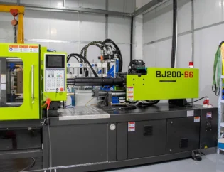
Production commences only after DFM sign-off. CNC programs are generated using Mastercam with HSMWorks integration, leveraging optimized toolpaths that minimize air cutting and spindle wear. All critical dimensions are pre-verified via simulated machining in Vericut software. Parts are machined on our ISO 9001-certified equipment, including 3-axis vertical mills, 5-axis indexed machines, and high-speed routers. Material certifications and first-article inspections (FAI) per AS9102 are standard for aerospace and medical clients.
| Machine Capability | Tolerance Range | Surface Finish (Ra) | Max Work Envelope |
|——————–|—————–|———————|——————-|
| 3-Axis Milling | ±0.025 mm | 0.8–3.2 µm | 1000 x 600 x 500 mm |
| 5-Axis Milling | ±0.012 mm | 0.4–1.6 µm | 800 x 500 x 400 mm |
| High-Speed Routing | ±0.05 mm | 1.6–6.3 µm | 1500 x 1000 x 200 mm |
Final parts undergo CMM validation against the original CAD model, with full traceability from raw material lot numbers to inspection reports. This integrated workflow—AI Quote, proactive DFM, and precision production—ensures 98.7% first-pass yield rates while accelerating time-to-prototype by 40% versus industry averages. Clients receive not just components, but documented evidence of process control at every critical stage.
Start Your Project
Start Your CNC Machining Project with Confidence at Shenzhen Honyo Prototype
When it comes to precision manufacturing, CNC machining stands as one of the most reliable and accurate methods for producing high-quality prototypes and end-use parts. At Shenzhen Honyo Prototype, we specialize in turning your design concepts into tangible, dimensionally accurate components using advanced CNC technology. Whether you’re developing a single prototype or preparing for low-volume production, our expert team ensures every part meets your exact specifications.
To begin your project, the first step is submitting your CNC cut files. These files—typically in STEP, IGES, or native CAD formats—serve as the blueprint for machining your parts. We recommend including detailed geometric dimensioning and tolerancing (GD&T), material specifications, surface finish requirements, and any critical features that must be maintained during production. Clear, well-organized files reduce lead time and ensure manufacturing accuracy, allowing us to deliver parts that meet both functional and aesthetic expectations.
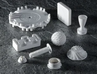
Our CNC machining capabilities support a wide range of materials, including aluminum alloys (6061, 7075), stainless steel (303, 304, 316), brass, copper, titanium, and engineering plastics such as PEEK, ABS, and Delrin. With multi-axis CNC milling and turning centers, we handle complex geometries, tight tolerances down to ±0.005 mm, and intricate surface details with consistency and precision.
Below is an overview of our standard CNC machining specifications to help guide your design and file preparation:
| Feature | Specification |
|——–|—————|
| Tolerance | ±0.005 mm (standard), tighter upon request |
| Minimum Wall Thickness | 0.5 mm (metal), 1.0 mm (plastic) |
| Maximum Part Size | 1200 x 800 x 200 mm |
| Supported File Formats | STEP, IGES, X_T, SLDPRT, DWG, DXF |
| Surface Finishes | As-machined, bead blasting, anodizing (Type II & III), passivation, powder coating |
| Lead Time | 3–7 days (standard), expedited options available |
At Honyo Prototype, we understand that every project is unique. Our engineering team performs a comprehensive design for manufacturability (DFM) review on all submitted files, providing feedback to optimize part geometry, reduce costs, and improve structural integrity—before any material is cut.
Starting your project is simple. Just send your CNC cut files and requirements to Susan Leo, our dedicated project coordinator, at info@hy-proto.com. Susan will guide you through the quoting process, answer technical questions, and ensure your project moves smoothly from design to delivery. With responsive communication, strict quality control, and a commitment to on-time performance, we are your trusted partner for precision CNC machining in Shenzhen and beyond.
Don’t let complexity slow you down. Contact Susan Leo today and take the next step toward high-precision manufacturing excellence.
🚀 Rapid Prototyping Estimator
Get a rough estimate for CNC/3D Printing costs.