Contents
Manufacturing Insight: Stl Files For Cnc Router
Manufacturing Insight: STL Files for CNC Router Applications
Understanding file format compatibility is critical when transitioning digital designs to physical parts via CNC routing. While STL (Stereolithography) files are ubiquitous in additive manufacturing, their application in CNC machining presents significant technical limitations that impact precision, efficiency, and final part quality. At Shenzhen Honyo Prototype, we frequently encounter clients mistakenly submitting STL files for CNC router projects, necessitating clarification on optimal workflows.
STL files represent 3D geometry as a tessellated mesh of triangular facets, inherently lacking critical manufacturing data such as continuous curvature (NURBS surfaces), precise edge definitions, and parametric history. CNC routers rely on exact vector paths derived from native CAD formats to generate efficient toolpaths. When forced to process STL data, CAM software must approximate smooth surfaces from discrete triangles, introducing unnecessary computational overhead and risking surface artifacts, dimensional inaccuracies, or excessive machining time. This approximation becomes particularly problematic for complex organic shapes or tight-tolerance features, where facet-induced “stair-stepping” can compromise functional performance. Consequently, STL files are ill-suited for CNC routing except in rare cases involving extremely low-precision, non-functional prototypes where surface finish is irrelevant.
Honyo engineers strongly recommend utilizing native CAD formats to maximize CNC router capabilities. The table below outlines preferred file types and their impact on manufacturability:
| Format | Native Use Case | CNC Router Suitability | Honyo Recommendation |
|——–|—————–|————————|———————-|
| STEP (.stp, .step) | Universal CAD exchange | Excellent | Preferred format; preserves geometry, tolerances, and metadata |
| IGES (.igs, .iges) | Legacy CAD exchange | Good | Acceptable alternative; may lose some parametric data |
| Parasolid (.x_t, .x_b) | Siemens NX/Solid Edge | Excellent | Ideal for complex multi-axis machining |
| STL (.stl) | 3D Printing | Poor | Not recommended; requires conversion, increases lead time and cost |
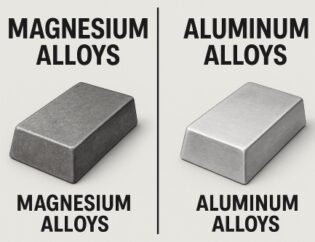
At Honyo, our Shenzhen-based CNC routing facilities leverage 3- to 5-axis routers with sub-0.05mm positional accuracy across materials including aerospace-grade aluminum, engineering plastics, and composite laminates. We process STEP, IGES, and Parasolid files directly into optimized G-code using industry-leading CAM suites, ensuring minimal tolerance stack-up and optimal tool engagement. This approach reduces machining time by up to 30% compared to STL-based workflows while guaranteeing surface finishes down to Ra 0.8μm. Our engineering team routinely assists clients in converting legacy STL data to manufacturable formats—adding value through geometry validation and manufacturability analysis—but emphasize that starting with the correct file format prevents rework and accelerates time-to-part.
Partnering with Honyo means leveraging our technical expertise to bridge the gap between design intent and physical reality. By prioritizing native CAD formats, manufacturers eliminate unnecessary conversion steps, reduce costs, and achieve higher fidelity in final components. Contact our Shenzhen engineering team for a complimentary file format assessment to optimize your next CNC router project.
Technical Capabilities
CNC Machining Technical Capabilities for STL File Processing
At Shenzhen Honyo Prototype, we specialize in precision CNC machining services tailored to customer-supplied STL files, enabling seamless translation of 3D digital models into high-accuracy physical prototypes and production parts. Our advanced 3-, 4-, and 5-axis milling capabilities, combined with CNC turning, allow us to handle complex geometries, undercuts, and multi-faceted features with exceptional repeatability and surface finish. STL files are processed through our in-house CAM software, where we validate geometry, optimize toolpaths, and ensure manufacturability while maintaining design intent.
Our 5-axis CNC routers provide full simultaneous motion, enabling single-setup machining of intricate contours and organic shapes commonly found in aerospace components, medical devices, and industrial enclosures. The integration of 4th and 5th axes reduces fixturing requirements and improves dimensional consistency, particularly for parts with angled features or non-orthogonal surfaces. For rotational symmetry and cylindrical components, our CNC turning centers deliver high-speed, tight-tolerance results, with the ability to perform secondary milling operations when required.
Tight tolerance machining is a core strength at Honyo Prototype. We consistently achieve tolerances down to ±0.005 mm for critical dimensions, with standard tolerances held to ±0.025 mm across most materials. Our quality control process includes pre-machining material inspection, in-process probing on select machines, and final verification using CMM and optical measurement systems. This ensures compliance with stringent industry standards and customer-specific requirements.
Material selection plays a critical role in achieving desired mechanical properties and surface quality. We support a broad range of engineering-grade plastics, metals, and composites suitable for functional testing and end-use applications. All materials are verified for machinability and compatibility with CNC routing processes to prevent warping, delamination, or tool wear.
The table below outlines our standard tolerance capabilities and supported materials for CNC machining from STL files:
| Material Category | Common Materials | Standard Tolerance (mm) | Tight Tolerance Capability (mm) | Max Part Size (mm) |
|——————-|——————|————————–|———————————-|——————–|
| Engineering Plastics | ABS, PC, POM (Delrin), Nylon, PEEK, PMMA | ±0.025 | ±0.010 | 1200 × 600 × 200 |
| Metals | Aluminum 6061, 7075, Stainless Steel 303, 316, Brass, Titanium | ±0.025 | ±0.005 | 1000 × 500 × 150 |
| Composites | Carbon Fiber Reinforced Polymers, G10, FR4 | ±0.050 | ±0.025 | 800 × 400 × 100 |
| Soft Tooling Materials | HDPE, Modeling Wax, Foam (EPS, PU) | ±0.050 | ±0.025 | 1500 × 800 × 300 |
All STL files should be exported with a minimum resolution of 0.05 mm chordal deviation to ensure smooth surface reproduction. We recommend watertight, manifold geometry with consistent normals and no self-intersections to avoid CAM processing delays. Upon receipt, our engineering team performs a free Design for Manufacturability (DFM) review to identify potential issues and suggest optimizations for cost and performance.
Shenzhen Honyo Prototype combines advanced CNC technology with rigorous quality systems to deliver precision-machined parts directly from your STL data—ensuring speed, accuracy, and reliability for prototyping and low-volume production.
From CAD to Part: The Process
From CAD to Physical Part: STL File Workflow for CNC Routing at Honyo Prototype
At Shenzhen Honyo Prototype, transforming a client’s digital concept into a precise physical part via CNC routing begins with robust file management, specifically handling STL files. This workflow ensures manufacturability and quality, moving seamlessly from initial inquiry through final production. The critical path involves three integrated phases: AI-Powered Quoting, Design for Manufacturability (DFM) Analysis, and CNC Production Execution.
The process initiates when a client submits an STL file through our online portal. Our proprietary AI quoting engine immediately performs a preliminary geometric assessment. It calculates bounding volume, estimates material usage based on the mesh density, and identifies potential red flags such as excessively high polygon counts causing file bloat or extremely small features below our routing capabilities. This rapid analysis generates an accurate, real-time cost and lead time estimate, setting clear expectations before engineering resources are deeply engaged. Crucially, the AI flags files requiring mandatory DFM review, preventing downstream delays.
All STL files, regardless of AI outcome, undergo rigorous DFM analysis by our engineering team. STL files present unique challenges for CNC routing compared to native CAD formats; they represent the surface as a mesh of triangles, not precise NURBS surfaces. Poor mesh quality directly translates to rough toolpaths and inaccurate parts. We validate key mesh parameters against our CNC router specifications and material constraints. Critical parameters include:
| Parameter | Typical Target Value | Reason for CNC Routing |
| :—————– | :——————- | :—————————— |
| Chord Height | ≤ 0.05 mm | Minimizes faceting on curves |
| Angular Tolerance | ≤ 1.0 degree | Ensures smooth surface transitions |
| Overall Resolution | Medium (Balanced) | Optimizes file size vs. accuracy |
We scrutinize for non-manifold edges, gaps, or flipped normals which cause toolpath generation failures. We verify minimum feature sizes against the smallest practical end mill (typically ≥ 1.5mm for wood/MDF, ≥ 3.0mm for acrylic) and assess undercuts or complex geometries requiring multi-axis machining or specialized fixturing not evident in the STL alone. Client collaboration is essential here; we provide specific, actionable feedback for design modifications to enhance manufacturability and reduce cost.
Upon DFM sign-off, the validated STL enters production. Our CAM software imports the STL and generates precise toolpaths, leveraging the cleaned mesh geometry. Tool selection, spindle speed, feed rate, and stepover are optimized for the specific material (e.g., plywood, HDPE, acrylic) and part geometry. Material is secured using optimized fixturing strategies developed during DFM. The CNC router executes the toolpaths with micron-level precision, monitored in real-time. Post-processing, including deburring and edge sanding, ensures the final part meets dimensional tolerances (typically ±0.1mm) and surface finish requirements specified during quoting.
This structured workflow—from AI-driven quoting through stringent DFM validation to precision CNC execution—ensures Honyo Prototype consistently delivers high-quality routed prototypes and low-volume production parts directly from client STL files, minimizing errors and maximizing efficiency in the digital-to-physical transition.
Start Your Project
Start Your CNC Router Project with Precision and Confidence
At Shenzhen Honyo Prototype, we understand that your manufacturing journey begins long before the first cut is made. It starts with a vision, a design, and the right partner to bring your concept to life. If you’re working with STL files and planning to use CNC router machining, you need more than just equipment—you need expertise in translating 3D digital models into high-precision physical parts. Whether you’re developing prototypes, custom components, or low-volume production runs, our team is equipped to support your project from file to finished part.
STL files are widely used in 3D printing, but adapting them for CNC routing requires careful interpretation. Unlike additive processes, CNC machining is subtractive, meaning toolpaths must be strategically planned to remove material efficiently while maintaining dimensional accuracy and surface finish. At Honyo Prototype, we specialize in converting STL data into optimized G-code for CNC routers, ensuring that your geometry is accurately represented in the final product. Our engineers analyze wall thicknesses, undercuts, tolerances, and material behavior to deliver parts that meet both functional and aesthetic requirements.
We support a wide range of materials, including aluminum, brass, engineering plastics, wood composites, and high-density foams—ideal for architectural models, jigs, fixtures, and consumer product prototypes. Our CNC routers offer large working envelopes and high repeatability, making them suitable for both detailed small parts and full-scale models.
To get started, simply send your STL file to our engineering team for a comprehensive review. We’ll assess manufacturability, suggest design improvements if needed, and provide a detailed quotation with lead time and pricing. Our goal is to streamline your development process, reduce time-to-market, and ensure first-time-right production.
Below are the key technical specifications for our CNC routing services:
| Parameter | Specification |
|—————————|———————————————–|
| Maximum Work Envelope | 1500 mm × 3000 mm × 200 mm |
| Positioning Accuracy | ±0.05 mm |
| Spindle Speed Range | 6,000 – 24,000 RPM |
| Supported File Formats | STL, STEP, IGES, DXF, DWG |
| Typical Tolerance | ±0.1 mm (standard), tighter on request |
| Surface Finish | Ra 3.2 µm (typical), finer with post-processing |
| Lead Time | 3–7 days (varies by complexity and volume) |
Your project deserves precision, reliability, and responsive support. Let us help you transition smoothly from digital design to physical reality.
Contact Susan Leo today at info@hy-proto.com to submit your STL file and receive a personalized manufacturing assessment. At Shenzhen Honyo Prototype, we’re not just service providers—we’re your manufacturing partners, committed to engineering excellence and customer success.
🚀 Rapid Prototyping Estimator
Get a rough estimate for CNC/3D Printing costs.