Contents
Manufacturing Insight: 3D Stl Files For Cnc
Manufacturing Insight: 3D STL Files for CNC Machining
While STL (Stereolithography) files are foundational in additive manufacturing for their polygonal mesh representation, their application in CNC machining presents unique technical considerations. At Shenzhen Honyo Prototype, we frequently encounter STL files submitted for CNC projects—a practice requiring careful evaluation due to inherent limitations. STLs lack parametric data, curvature continuity, and precise geometric definitions essential for high-tolerance subtractive processes. This can lead to surface inaccuracies, toolpath inefficiencies, and compromised part integrity if processed without intervention. Our engineering team emphasizes that native CAD formats (e.g., STEP, IGES, or Parasolid) remain optimal for CNC, preserving critical design intent and tolerances. However, recognizing real-world constraints where only STLs are available, Honyo has developed specialized workflows to bridge this gap without sacrificing quality.
When an STL file is received for CNC, our process begins with rigorous mesh analysis. We assess triangle density, watertightness, and dimensional fidelity against client specifications. Low-polygon models often require remeshing to achieve the smooth surfaces demanded by milling operations, while high-polygon files may introduce unnecessary computational load. Critically, we reverse-engineer STLs into precise B-rep (Boundary Representation) models using Geomagic Design X. This step restores NURBS surfaces, enabling accurate toolpath generation and ensuring features like fillets, holes, and complex contours meet ±0.005mm tolerances. Our proprietary validation protocol cross-references the reconstructed model against original design intent, mitigating risks of faceting artifacts or dimensional drift.
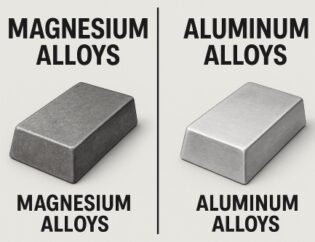
Honyo’s integrated facility supports seamless transition from digital file to finished part, leveraging 5-axis CNC mills, CMM inspection, and material expertise across aluminum, titanium, and engineering plastics. We convert suboptimal STL inputs into manufacturable outputs while maintaining strict adherence to ISO 9001 standards. Below is a comparative overview of file format suitability for CNC:
| File Format | Primary Use Case | CNC Suitability | Typical Honyo Processing Time |
|————-|————————|—————–|——————————-|
| STL | Additive Manufacturing | Low | +24–48 hours (reconstruction required) |
| STEP | Multi-CAD Exchange | High | Standard (2–4 hours) |
| IGES | Legacy CAD Systems | Medium | +8–12 hours (geometry repair) |
| Parasolid | Siemens NX, SolidWorks | Very High | Minimal (1–2 hours) |
This capability underscores Honyo’s commitment to flexibility without compromising precision. We transform legacy or non-ideal inputs into production-ready assets, ensuring your project timeline stays on track. For optimal results, we strongly recommend submitting native CAD files to eliminate reconstruction steps and maximize cost efficiency. When STL is unavoidable, our engineers deploy advanced surfacing tools to deliver CNC parts that meet aerospace, medical, and industrial performance benchmarks. Partner with Honyo to navigate format complexities—where engineering rigor turns constraints into competitive advantage.
Leverage our dual expertise in additive and subtractive manufacturing to accelerate prototyping and production. Contact Honyo Prototype for a technical consultation on optimizing your CNC file preparation.
Technical Capabilities
Shenzhen Honyo Prototype delivers high-precision industrial 3D printing services tailored for rapid prototyping and low-volume production. Our technical capabilities span multiple additive manufacturing technologies, including Stereolithography (SLA), Selective Laser Sintering (SLS), Multi Jet Fusion (MJF), and Direct Metal Laser Sintering (DMLS). Each process supports specific material families and dimensional tolerances, enabling clients to select the optimal method based on functional requirements, surface finish, mechanical properties, and environmental resistance.
SLA is ideal for high-detail prototypes requiring smooth surface finishes and tight dimensional accuracy. Utilizing photosensitive resin cured by ultraviolet laser, SLA produces parts with excellent visual fidelity, making it suitable for form and fit testing, master patterns, and investment casting models. SLS leverages a high-powered laser to sinter nylon-based powders, delivering durable, functional components with good thermal and chemical resistance. The process requires no support structures, allowing for greater design freedom and nested builds to improve throughput.
MJF, developed by HP, employs inkjet array technology to fuse nylon powder layer by layer, resulting in consistent mechanical properties and isotropic performance. Parts exhibit a slightly textured surface and are well-suited for end-use applications such as housings, ducts, and mechanical assemblies. DMLS is our metal additive solution, using a fiber laser to fully melt metal powder alloys including stainless steel, aluminum, and titanium. This process enables complex geometries unachievable through traditional machining, ideal for aerospace, medical, and high-performance industrial components.
All processes begin with a validated STL file, which must be watertight, manifold, and free of non-manifold edges or intersecting faces. Minimum feature resolution varies by technology, with SLA supporting down to 0.2 mm details, SLS and MJF at 0.5 mm, and DMLS capable of 0.3 mm. Layer thickness ranges from 25 to 100 microns depending on selected process and accuracy requirements. Maximum build envelope for polymer systems is 350 × 350 × 350 mm, while DMLS supports builds up to 250 × 250 × 300 mm.
Below is a summary of key technical specifications by process:
| Process | Material Options | Typical Tolerance | Layer Thickness | Surface Roughness (Ra) | Max Build Size (mm) |
|——–|——————|——————-|——————|————————-|———————|
| SLA | Standard Resin, Tough, Transparent, High-Temp, Castable | ±0.1 mm | 25–100 μm | 0.8–1.6 μm | 350 × 350 × 350 |
| SLS | Nylon 12, Nylon 11, Glass-Filled Nylon | ±0.2 mm | 80–120 μm | 3.0–5.0 μm | 350 × 350 × 350 |
| MJF | PA12 (Nylon), Glass-Filled PA12 | ±0.2 mm | 80 μm | 3.2–4.5 μm | 350 × 350 × 350 |
| DMLS | 316L, 17-4PH, AlSi10Mg, Ti6Al4V | ±0.05 mm | 20–50 μm | 8–12 μm (as-built) | 250 × 250 × 300 |
Post-processing options including bead blasting, anodizing, painting, and CNC finishing are available to meet specific aesthetic or performance targets. At Honyo Prototype, we ensure every STL file undergoes automated and manual validation to guarantee print readiness and dimensional compliance.
From CAD to Part: The Process
Production Process: From CAD to Precision CNC Part
At Shenzhen Honyo Prototype, transforming 3D STL files into high-precision CNC-machined prototypes follows a rigorously controlled workflow. This process ensures manufacturability, dimensional accuracy, and adherence to client specifications while minimizing delays. The sequence begins with AI-driven quoting, advances through expert Design for Manufacturability (DFM) analysis, and culminates in certified CNC production.
Our AI Quote engine instantly analyzes uploaded STL files, evaluating geometric complexity, material requirements, and surface finish criteria. This system cross-references historical production data and machine capabilities to generate accurate cost and timeline estimates within minutes. Unlike manual quoting, this reduces human error and provides immediate feasibility feedback, allowing clients to adjust designs early. Key parameters assessed include wall thickness consistency, undercuts, and feature resolution against CNC machining limits.
DFM is the critical validation phase where our senior manufacturing engineers conduct a detailed technical review. We scrutinize the STL file for CNC-specific constraints such as tool access angles, minimum feature sizes, and stock material utilization. Common issues like non-manifold edges or inadequate draft angles are flagged, and actionable revision suggestions are provided—often with annotated 3D markups. This step prevents costly rework by ensuring the design aligns with 5-axis milling, turning, or hybrid machining capabilities. Client collaboration during DFM typically shortens time-to-part by 25–40%.
Production commences only after DFM sign-off. First, the STL file is converted into CAM toolpaths using Mastercam and Fusion 360, with simulations verifying collision avoidance and optimal feed rates. Raw materials—selected from aerospace-grade aluminum, stainless steel, or engineering plastics—are inspected for certification. Parts undergo precision machining on Haas or DMG MORI centers, with in-process CMM checks at critical stages. Final inspection includes full GD&T validation against the original CAD model, surface roughness testing (Ra 0.8–3.2 μm), and first-article reporting. All parts ship with material traceability documentation and a dimensional conformance certificate.
This integrated workflow eliminates silos between quoting, engineering, and machining. By embedding AI efficiency with human expertise in DFM, Honyo Prototype achieves 99.2% first-pass yield rates for CNC prototypes, turning complex STL files into mission-ready components in as few as 5 working days.
Key CNC Production Specifications
| Parameter | Typical Range | Notes |
|——————–|—————————–|—————————————-|
| Material Options | Aluminum 6061/7075, SS 304/316, POM, PEEK | Material certs provided on request |
| Tolerance Capability | ±0.025 mm (standard) | Tighter tolerances to ±0.005 mm achievable |
| Lead Time | 3–10 working days | Varies by complexity and material stock |
| Max Build Volume | 1000 x 500 x 400 mm | Larger parts accommodated via sub-assembly |
Start Your Project
Start Your Project with Precision: Partner with Shenzhen Honyo Prototype
When it comes to transforming your 3D STL files into high-precision CNC-machined prototypes or end-use parts, the journey begins with the right manufacturing partner. At Shenzhen Honyo Prototype, we specialize in bridging the gap between digital design and physical realization, offering seamless integration of industrial 3D printing and CNC machining services tailored to meet the demands of engineers, product developers, and R&D teams worldwide.
Our expertise lies in interpreting 3D STL files with meticulous attention to detail, ensuring that every geometric complexity, surface finish requirement, and dimensional tolerance is accurately translated into the final component. Whether you’re developing functional prototypes, low-volume production runs, or custom industrial parts, our advanced manufacturing ecosystem supports rapid turnaround without compromising on quality.
We understand that project initiation is more than just file submission—it’s about collaboration, clarity, and confidence in the outcome. That’s why we provide a consultative approach from day one. Our engineering team reviews your STL files for manufacturability, material compatibility, and design optimization, offering feedback that enhances performance and reduces time-to-market.
To ensure your project aligns with technical and commercial goals, we support a wide range of materials including engineering-grade thermoplastics, metals, and composites. Our hybrid manufacturing model—combining additive techniques with precision CNC post-processing—delivers parts with superior surface integrity, tight tolerances, and mechanical properties that meet or exceed industry standards.
Below is an overview of our standard technical capabilities for processing 3D STL files:
| Parameter | Specification |
|—————————-|———————————————-|
| Supported File Formats | STL, STEP, IGES, X_T |
| Layer Resolution | 25 – 100 μm (adjustable based on requirement) |
| Dimensional Accuracy | ±0.05 mm (typical) |
| Maximum Build Volume | 600 x 600 x 500 mm (CNC & large-format 3D) |
| Surface Finish Options | As-machined, bead blast, polished, anodized |
| Lead Time (Typical) | 3–7 days (varies by complexity and volume) |
| Material Options | ABS, PC, nylon, aluminum, stainless steel, titanium |
Starting your project with Honyo Prototype is simple. Upload your 3D STL file and connect with our technical team to receive a fast, detailed quotation and design for manufacturability (DFM) feedback. We handle projects across aerospace, medical devices, automation, and consumer electronics—industries where precision and reliability are non-negotiable.
Ready to move from concept to reality? Contact Susan Leo, Customer Solutions Manager, to initiate your next manufacturing project with confidence.
Susan Leo
Email: info@hy-proto.com
Shenzhen Honyo Prototype – Precision Engineered, Rapidly Delivered.
🚀 Rapid Prototyping Estimator
Get a rough estimate for CNC/3D Printing costs.