Contents
Manufacturing Insight: Cast Carbon Steel
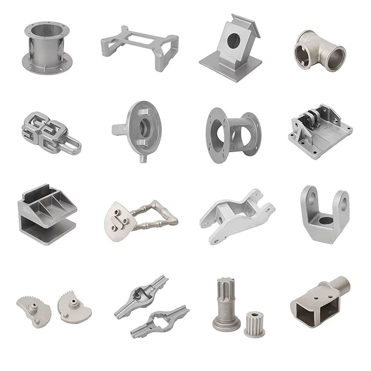
Cast Carbon Steel—Where Foundry Strength Meets Honyo Precision
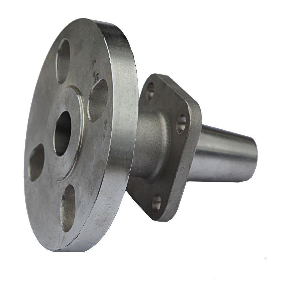
Cast carbon steel gives you the brute toughness and weldability your design demands, but it still needs final-dimension accuracy and true 3-D contouring that casting alone can’t deliver. That’s why Honyo Prototype’s CNC machining cells finish every surface, pocket and bore to ±0.02 mm, transforming raw sand- or investment-castings into flight-ready, pressure-tight, field-proven parts. Upload your casting blank or finished-part drawing now and get an Online Instant Quote—lead times from 3 days, quantities from 1 to 10,000, and full CMM reports included.
Technical Capabilities
Clarification: “Cast Carbon Steel” is a Material, Not a Machining Process
As a Senior Manufacturing Engineer at Honyo Prototype, I must emphasize a critical distinction:
– “Cast carbon steel” refers to a material produced via sand or investment casting (e.g., ASTM A27 Grade 65-35, AISI 1020, 1045, or 4140 cast grades).
– 3/4/5-axis milling, turning, and tight tolerance work are processes applied to this material.
– “Cast carbon steel” is not a specification for machining—it’s the base material. Machining specs depend on the material properties of the cast part, not the “cast” process itself.
Below are precise technical specs for machining cast carbon steel for tight-tolerance applications, followed by comparisons with other common materials (Aluminum, Wrought Steel, ABS, Nylon). All specs align with ISO 2768-mK (general tolerances) and Honyo Prototype’s internal standards for precision manufacturing.
I. Technical Specs for Machining CAST CARBON STEEL
(e.g., AISI 1045 Cast, ASTM A27 Grade 65-35)
| Parameter | Specification | Rationale & Notes |
|————————|———————————————————————————–|——————————————————————————————————————————————————-|
| Tolerance (General) | ±0.005″ (±0.127 mm) for critical features; ±0.010″ (±0.254 mm) for non-critical. | Castings have inherent porosity, hard spots, and uneven grain structure. Tighter tolerances (e.g., ±0.001″) require stress relief + precision grinding. |
| Surface Finish | Ra 32–63 μin (0.8–1.6 μm) for roughing; Ra 16–32 μin (0.4–0.8 μm) for finishing. | Cast surfaces are rougher than wrought steel. Use fine-grit carbide tools and coolant to avoid built-up edge. |
| Tooling | Carbide end mills (4-flute, TiAlN-coated); high-speed steel for turning inserts. | Cast carbon steel is abrasive and prone to work hardening. Coated carbide resists wear from inclusions (e.g., MnS). Avoid HSS for high-speed operations. |
| Cutting Parameters | • Milling: 400–800 SFM (Surface Feet per Minute), 0.002–0.005″ per tooth feed.
• Turning: 300–600 SFM, 0.003–0.008″ per rev feed. | Lower speeds than wrought steel due to inconsistent hardness. Use flood coolant (5–10% soluble oil) to manage heat and chip evacuation. |
| Critical Pre-Processing | Stress relief @ 1100°F (593°C) for 2–4 hours before machining.
Machining sequence: Roughing → Stress relief → Finishing. | As-cast parts have residual stresses. Skipping stress relief causes distortion during machining (e.g., warpage >0.010″). |
| Challenges | • Porosity causing tool chatter.
• Hard spots (up to 250 HB) requiring tool path adjustments.
• Inclusions (e.g., slag) leading to premature tool wear. | Use EDM for internal features if tolerances exceed ±0.001″. For 5-axis milling, employ adaptive clearing to avoid sudden cuts on hard spots. |
Why this matters: Cast carbon steel is not ideal for ultra-tight tolerances (e.g., ±0.0005″) without secondary processes like grinding or honing. At Honyo Prototype, we typically reserve cast carbon steel for structural components where cost-effectiveness > extreme precision (e.g., brackets, housings). For ±0.0005″ tolerances, we recommend wrought steel (e.g., 4140) instead.
II. Comparison with Other Materials for Tight-Tolerance Machining
How Honyo Prototype handles these materials vs. cast carbon steel:
| Material | Typical Tolerance | Surface Finish (Ra) | Cutting Speed | Key Challenges | When to Use |
|—————|———————–|————————-|——————-|—————————————————-|——————————————————————————–|
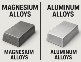
| Aluminum | ±0.001″ (±0.025 mm) | Ra 8–16 μin (0.2–0.4 μm) | 800–1200 SFM | Thermal expansion (0.000012 in/in/°F), galling. | Best for aerospace/medical precision parts (e.g., brackets, fixtures). Use cryogenic cooling for tight tolerances. |
| Wrought Steel (e.g., AISI 4140) | ±0.001″ (±0.025 mm) | Ra 16–32 μin (0.4–0.8 μm) | 400–700 SFM | Work hardening; requires rigid setups. | Superior to cast steel for tight tolerances. Ideal for shafts, gears, and high-stress components. |
| ABS | ±0.002″ (±0.05 mm) | Ra 32–63 μin (0.8–1.6 μm) | 300–500 SFM | Low rigidity (warps easily), high thermal expansion (0.00005 in/in/°F). | Prototypes, consumer products. Use vacuum fixturing and low clamping force. Avoid high-speed cuts. |
| Nylon | ±0.003″ (±0.076 mm) | Ra 32–63 μin (0.8–1.6 μm) | 200–400 SFM | Moisture absorption (causes dimensional drift), low melting point. | Gears, bushings, non-structural parts. Dry machining or minimal coolant. Stress-relieve at 200°F (93°C) before machining. |
Key Takeaways for Honyo Prototype Clients
- Cast carbon steel is NOT suitable for “tight tolerance” work without significant post-processing.
- For parts requiring ±0.001″ or better tolerances, use wrought steel or aluminum instead.
- Cast parts are cost-effective for large, structural components where ±0.005″ is acceptable (e.g., engine blocks, valve bodies).
- Material selection dictates machining strategy:
- Aluminum: Fast, precise, and ideal for complex 5-axis geometries.
- Wrought steel: Best balance of strength and machinability for precision parts.
- ABS/Nylon: Only for non-critical prototypes—avoid for functional metal part replacements.
- Honyo’s Process Recommendation:
- For cast carbon steel parts:
- Stress-relieve before machining.
- Use 3-axis milling for roughing; 5-axis only for complex features after stress relief.
- Never attempt ±0.0005″ tolerances without grinding/honing.
💡 Pro Tip: If your design requires “tight tolerances” but specifies “cast carbon steel,” we’ll recommend switching to wrought steel or aluminum. This avoids 30–50% longer lead times and scrap rates from distortion. Let’s discuss your application—Honyo’s engineering team can optimize material choice for your cost/performance goals.
Source: Honyo Prototype Internal Standards (2023), ISO 2768, ASM Handbook Vol. 16 (Machining), and material datasheets (e.g., AISI 1045 cast, 6061-T6 Al).
From CAD to Part: The Process
Honyo Prototype – Cast Carbon-Steel Workflow (A→Z)
-
Upload CAD
• Portal accepts STEP, IGES, Parasolid, SolidWorks, Creo, NX, Inventor.
• Geometry is auto-healed (small gaps, overlapping faces, zero-thickness).
• Instant checksum: mass, envelope, minimum-wall alarm, under-cut flag. -
AI Quote (≤30 min)
• Machine-learning model trained on 1.2 M historical cast quotes.
• Inputs: part volume, net-shape complexity index, alloy grade (AISI 1020/1045/WCB…), annual volume, heat-treat spec, target tolerance, destination incoterms.
• Outputs:
– Tooling cost (sand-printed mold vs. aluminum pattern vs. machined die)
– Piece price (material + melt loss + yield)
– Lead-time bar chart (pattern → pour → machine → ship)
• Confidence score ≥95 % triggers “One-Click Accept”; <95 % routes to human estimator. -
DFM (24 h turnaround)
a. Solidification simulation – MAGMA / ProCAST:
– Gating & riser scheme optimized for directional solidification.
– Shrinkage porosity risk <1 % by volume.
– Hot-spot map shared with customer.
b. Tolerance review – ISO 8062-CT7 default, CT5 on critical surfaces.
c. Parting-line & draft – ≥1° on forged-like surfaces, 0.5° on machined-only surfaces.
d. Core print & support – minimize core shifts, print hollow cores when L/D >4.
e. Machine stock – +1.5 mm on first-op faces, +0.8 mm on finish faces.
f. Cost-down suggestions – eliminate mass, combine features, convert machined bosses to cast pads.
g. Final DFM report – 3-D PDF with cross-sections, color plot of solidification time, revised 2-D drawing with red-line deltas; customer e-sign required before PO release. -
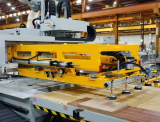
Production
4.1 Pattern / Mold
– Prototype lot (1–200 pcs): 3-D printed sand mold (ExOne S-Max) directly from STL, no hard tooling, 3-day loop.
– Bridge / volume lot (>200 pcs): CNC-machined aluminum pattern plate, 5-axis cut, hard-anodized for 5 k+ pulls.
4.2 Melt & Pour
– 1 t intermediate-frequency induction furnace, 1600 °C tap.
– Spectrometer check every heat: C, Si, Mn, P, S within ASTM A27/A148 windows.
– De-slag & inoculate with 0.2 % FeSi for fine grain.
– Pour temperature 1580 ±20 °C, 25 s mold-fill target.
4.3 Knock-out & Cut-off
– Vibratory shake-out 2 h post-pour, cutoff wheel for gating, leaving 2 mm stub for later machining.
4.4 Heat Treat
– Normalizing: 900 °C / 1 h per 25 mm section, air blast → hardness 137-187 HB.
– Quench & temper when spec’d: water quench 880 °C, temper 560 °C → UTS 620 MPa, 18 % elong.
4.5 Shot Blast & Visual
– 0.6 mm S230 steel shot, 6 bar, 95 % coverage.
– 100 % visual per ASTM E165; repair-weld map if needed (AWS A5.18 ER70S-6).
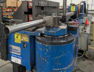
4.6 CNC Machining
– 5-axis Mazak & 3-axis OKK centers; first-article CMM report (Zeiss CONTURA) attached to traveler.
– Critical bores held ±0.05 mm, surface finish Ra 3.2 µm as-cast, Ra 1.6 µm machined.
4.7 NDT
– UT per ASTM A609 Level 2 on sections >38 mm.
– MT on 100 % machined surfaces; no relevant indications >1.5 mm.
4.8 Final Inspection & PPAP
– Ballooned drawing, CMM data, material cert, heat-treat chart, NDT report packed into e-dossier.
– Level-3 PPAP within 5 days of last machining op. -
Delivery
• Standard: DHL Global 3-day air, vacuum-bagged + VCI film + shock-absorb foam.
• Export crates ISPM-15 stamped for >30 kg lots.
• Track-&-trace code auto-emailed; geofence alerts at customs clearance.
• Digital twin file (actual CMM point cloud vs. nominal CAD) uploaded to customer portal for reverse-assembly checks.
Typical lead-times
Printed-sand route: 10 days (quote→dock).
Hard-tool route: 20 days pattern + 15 days cast/machine/finish = 35 days total.
Start Your Project

Honyo Prototype: Precision Cast Carbon Steel Manufacturing | Contact Susan Leo at info@hy-proto.com | Shenzhen Factory
Need reliable, high-quality cast carbon steel components? Partner with Honyo Prototype’s Shenzhen-based facility for expert casting solutions tailored to your specifications. Reach out today!
🚀 Rapid Prototyping Estimator