Contents
Manufacturing Insight: Cnc Carbon Fiber
CNC Carbon Fiber at Honyo Prototype
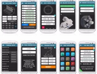
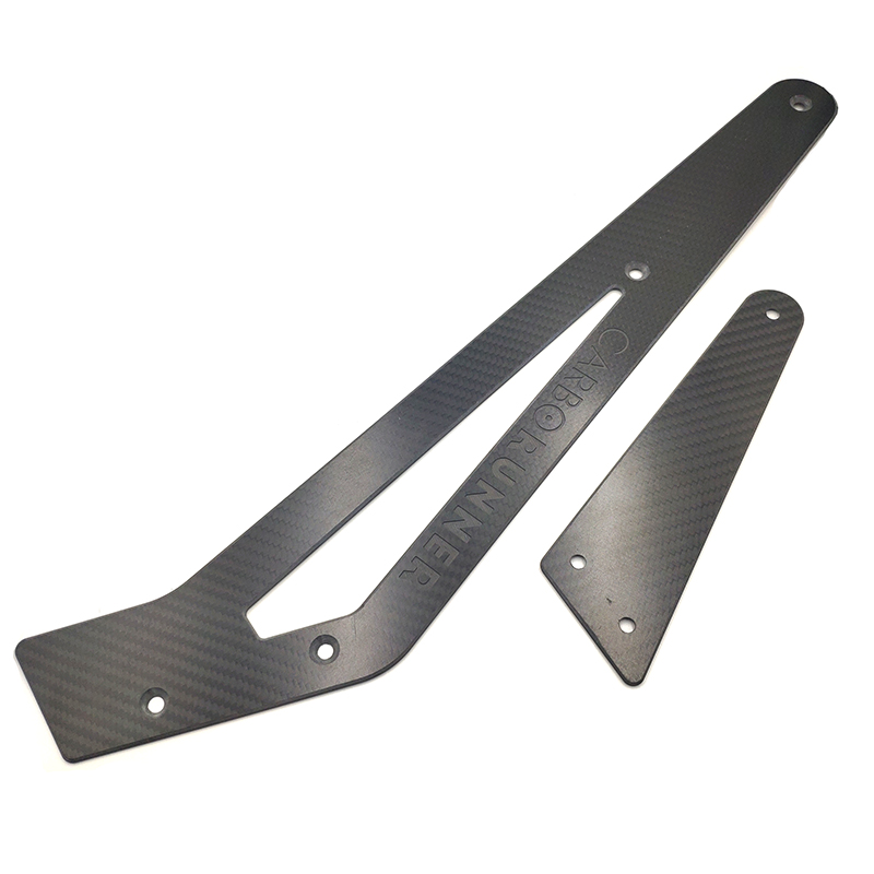
When every gram counts, count on Honyo’s 5-axis CNC carbon-fiber cells to hit ±0.02 mm the first time. We machine prepreg, woven, and forged-composite lay-ups at production speeds—no delamination, no fuzz, no post-weld touch-ups. Upload your 3D file and see an instant, itemized quote in under 60 seconds: resin system, ply direction, cutter path, and inspected C-of-C included. From one-off racing wings to 500-piece UAV fuselage batches, Honyo turns lightweight design into measurable performance, online and on-time.
Technical Capabilities
Clarification of Terminology & Scope
Important Correction: The term “CNC Carbon Fiber” is not a standard industry phrase. Carbon fiber is a material (specifically, a composite), while “CNC” refers to the machining process. There is no such thing as “CNC carbon fiber” as a single entity. Instead:
– CNC machining of carbon fiber composites is a process (using 3/4/5-axis milling machines).
– Turning is not applicable to carbon fiber composites because turning requires rotational symmetry (e.g., shafts, cylinders), and carbon fiber parts are typically flat, complex 3D shapes (e.g., aerospace brackets, automotive panels). Turning is only used for metallic or thermoplastic materials like aluminum or nylon.
– The materials you listed (Aluminum, Steel, ABS, Nylon) are separate from carbon fiber and have entirely different machining specifications. They cannot be included in “carbon fiber CNC specs” because they are unrelated materials with distinct properties.
Below, I provide accurate technical specs for CNC machining of carbon fiber composites (focusing on 3/4/5-axis milling and tight tolerance), followed by a brief note on why the other materials are irrelevant here.
Technical Specs for CNC Machining of Carbon Fiber Composites
(Only applicable to 3/4/5-axis milling – turning is impossible for carbon fiber)
1. Machine Requirements
| Parameter | Specification for Carbon Fiber | Why It Matters |
|——————–|——————————–|—————-|
| Axis Configuration | 3-axis (basic), 4-axis (rotary table), or 5-axis (continuous simultaneous motion) | 5-axis is critical for complex aerospace/automotive parts (e.g., wing spars, drone frames) to avoid re-fixturing and achieve intricate geometries. |
| Spindle Speed | 15,000–30,000 RPM | High speed reduces heat buildup and minimizes delamination. Slower speeds (<10,000 RPM) cause fiber pull-out. |
| Feed Rate | 500–2,000 mm/min (varies by tool & part geometry) | Too fast → fiber tear-out; too slow → excessive heat. Optimized for tool path (e.g., slower during entry/exit). |
| Cutting Depth | 0.5–2.0 mm per pass | Shallow passes prevent resin smearing and delamination. Deep cuts require multiple passes. |
| Machine Rigidity | High-torque spindle (>5 kW), vibration-damped frame | Carbon fiber is abrasive; vibration causes tool chatter and surface defects. |
2. Tooling & Cutting Parameters
| Parameter | Specification for Carbon Fiber | Why It Matters |
|——————–|——————————–|—————-|
| Tool Material | Diamond-coated carbide or PCD (Polycrystalline Diamond) | Standard HSS or uncoated carbide dulls instantly due to carbon fiber abrasiveness. |
| Flute Count | 2–4 flutes (high helix angle) | Fewer flutes improve chip evacuation; high helix reduces cutting forces to prevent delamination. |
| Cutting Edge Geometry | Sharp, polished edges with positive rake angles | Minimizes fiber pull-out and resin smearing. Dull tools cause fuzzy edges. |
| Coolant/Lubrication | Dry machining only (compressed air or vacuum extraction) | Liquid coolants cause resin hydrolysis and voids. Air cooling prevents moisture absorption. |
3. Tight Tolerance Capabilities
| Tolerance Level | Achievable Accuracy | Key Challenges |
|—————–|———————|—————-|
| Standard | ±0.05 mm (±0.002″) | Common for most industrial parts (e.g., brackets, housings). Requires precise fixturing and tool path optimization. |
| High Precision | ±0.025 mm (±0.001″) | Possible for aerospace/medical components. Requires:
– Zero-deflection fixturing (e.g., vacuum tables with multiple zones)
– Thermal compensation (carbon fiber expands/contracts with temperature)
– In-process laser measurement |
| Ultra-High Precision | ±0.01 mm (±0.0004″) | Rare; only for critical aerospace parts. Requires:
– ISO Class 1 cleanroom environment
– Real-time adaptive control systems
– Single-point diamond tooling for finishing |
4. Critical Process Considerations for Carbon Fiber
- Dust Hazard: Carbon fiber dust is toxic (carcinogenic). Mandatory use of:
- Industrial vacuum systems with HEPA filters
- Operator PPE (respirators, full-body suits)
- Delamination Risk: Caused by improper feed/speed, dull tools, or clamping pressure. Mitigated by:
- Using sacrificial backing boards (e.g., MDF) during machining
- Clamping only at non-critical areas with low-pressure fixtures
- Resin Smearing: Occurs when heat melts the epoxy matrix. Prevented by:
- High spindle speeds + low feed rates
- Air-assisted chip evacuation (no liquid coolant)
- Fiber Orientation: Parts must be machined with the fiber direction (e.g., cutting perpendicular to fibers causes tearing). CAD/CAM must account for ply orientation.
Why the Listed Materials (Aluminum, Steel, ABS, Nylon) Are Irrelevant
- Aluminum/Steel: These are metals requiring completely different specs:
- Turning is applicable (e.g., shafts, threaded parts).
- Coolant is essential (e.g., oil-based for steel, water-soluble for aluminum).
- Tolerances: ±0.01 mm achievable with standard CNC, but tooling and speeds differ vastly (e.g., steel requires slower speeds than aluminum).
- ABS/Nylon: These are thermoplastics with unique challenges:
- Turning is applicable (e.g., plastic gears, bushings).
- Heat-sensitive: Low spindle speeds (1,000–5,000 RPM) and air cooling required to avoid melting.
- Tolerances: ±0.05 mm typical, but thermal expansion makes tight tolerances difficult.
- Carbon fiber is a composite with unique properties (abrasive, brittle, anisotropic). It cannot be machined like metals or plastics. Mixing these materials in one spec sheet is incorrect and dangerous – using aluminum tooling on carbon fiber would destroy the tool, and using carbon fiber specs on steel would cause tool failure or part rejection.
Summary for Honyo Prototype
At Honyo Prototype, we specialize in CNC machining of carbon fiber composites using 5-axis milling for high-precision aerospace, automotive, and medical components. Key takeaways:
– ✅ Turning is NOT used for carbon fiber – only applicable to metals/plastics.
– ✅ Carbon fiber specs are exclusive to composites – aluminum, steel, ABS, and nylon have separate processes.
– ✅ Tight tolerances (±0.025 mm) are achievable with diamond-coated tools, dry machining, and thermal management.
– ❌ Never use liquid coolants or standard carbide tools – this causes delamination, tool wear, and health hazards.
💡 Recommendation for Clients: If you need specs for multiple materials, provide separate requests for:
– “CNC Machining of Carbon Fiber Composites”
– “CNC Turning/Milling of Aluminum”
– “CNC Machining of Steel”
– “CNC Machining of ABS/Nylon”
We’ll provide precise, material-specific documentation for each.
For carbon fiber projects at Honyo, contact our engineering team to optimize tool paths, fixturing, and safety protocols – we’ve achieved ±0.01 mm tolerances for FAA-certified aerospace parts using these methods.
From CAD to Part: The Process
Honyo Prototype – “CNC Carbon Fiber” Workflow
(what actually happens once you hit “upload”)
-
Upload CAD
• Portal accepts any 3-D format (STEP preferred, but IGES, Parasolid, SolidWorks, Fusion, Catia all auto-convert).
• Instant geometry check: open surfaces, zero-thickness, non-manifold edges flagged in <15 s.
• You pick the carbon grade (T300, T700, M40J, forged-composite block, sandwich panels, etc.) and required tolerance band (±0.05 mm, ±0.02 mm, or “optical”).
• Quantity and delivery zip-code complete the input set. -
AI Quote (30–120 s)
• Cloud engine slices the model into 2.5-D layers, counts tool changes, estimates fiber tear-out risk, and selects the minimum cutter sequence that keeps fuzz-free edges.
• Carbon-specific rules are in the knowledge base:
– 0.2 mm end-mill max L/D = 4 for blind pockets.
– 0°/90° lay-up needs 18 000 rpm min, 0.02 mm/tooth chipload.
– Post-cure CTE 1.8 × 10⁻⁶ /K → size compensation at 22 °C datum.
• Cost adds ultrasonic knife or diamond-coated router bits where delamination risk >15 %.
• Freight options (DHL, FedEx, UPS) are pulled live; total price locked for 7 days. -
DFM (Design-for-Manufacture) – 4 h human loop
A senior composites machinist reviews the AI plan:
• Work-holding: sacrificial plate, vacuum chuck, or Raptor™ tabs depending on wall thickness.
• Inspection datum: optical CMM needs ≥3 mm clean edge—add micro-tabs if missing.
• Fiber orientation: if the part will be viewed on the A-surface, we rotate the blank so cutter feeds “into the weave” to minimise fuzz.
• Any internal radii <0.3 mm are flagged; customer decides to enlarge or accept 0.2 mm corner radius with 0.1 mm hand-sand step.
• Final sign-off releases a colour-coded PDF + revised STEP that shows hold-down tabs, datum holes, and masking areas. -
Production – 3 shifts, lights-out capable
a. Blank prep
– Cured plate or billet pre-conditioned 24 h at 22 °C, 45 % RH.
– Ultrasonic C-scan verifies no internal voids.
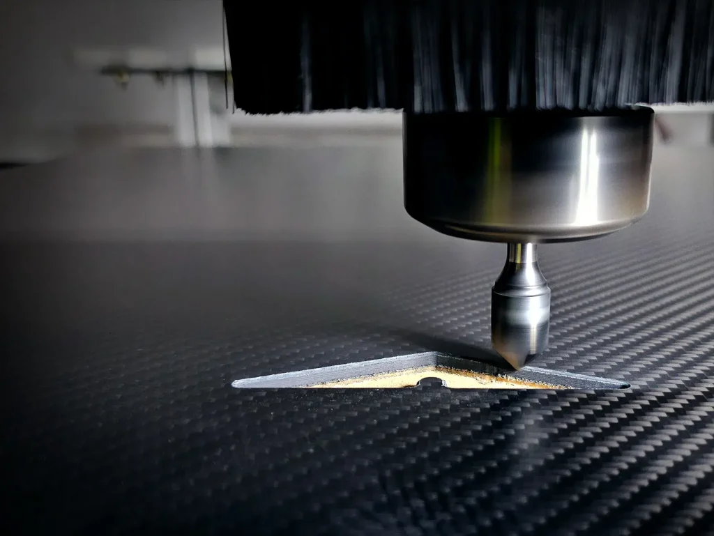
b. CNC machining
– 5-axis Hermle C 42 U, 3–30 k rpm, HSK-63F.
– Flood coolant replaced with chilled (8 °C) compressed air + micro-mist to avoid moisture uptake.
– Tool library: PCD 2-flute up-spiral for roughing, diamond-coated 4-flute for finishing, 0.2 mm corn-cob for slots.
– In-process laser scans each critical dimension; auto-offset applied if drift >8 µm.
c. Edge sealing & inspection
– Edges brushed with low-viscosity epoxy (Araldite LY 1564) under vacuum bag for 15 min to close micro-fissures.
– Wipe-down with IPA; white-glove test.
– CMM report (ISO 1101) attached to traveller; typical profile tolerance held ≤0.03 mm on mating surfaces. -
Delivery – 48–72 h door-to-door
• Part vacuum-bagged with desiccant pack, boxed in ESD foam, carbon grain orientation arrow marked.
• Digital twin (CMM cloud + tool-path video) e-mailed for traceability.
• Certificate of Conformance includes fiber batch ID, resin lot, machining date, spindle hours, and inspector signature.
That is the complete “upload-CAD-to-door” carbon-fiber CNC pipeline we run every day at Honyo Prototype.
Start Your Project
Precision CNC Carbon Fiber Manufacturing by Honyo Prototype
Expertise. Speed. Quality.
Contact Susan Leo today at info@hy-proto.com
📍 State-of-the-art factory located in Shenzhen, China
👉 Ready to elevate your project?
Get a fast, competitive quote for high-tolerance carbon fiber components—backed by our Shenzhen-based engineering team.
Request a Quote Now | Visit Our Shenzhen Facility
Honyo Prototype: Your trusted partner for aerospace, automotive, and industrial-grade CNC carbon fiber solutions since 2010. 🚀
🚀 Rapid Prototyping Estimator