
Contents
Manufacturing Insight: Cnc Cutting Files
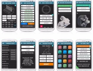
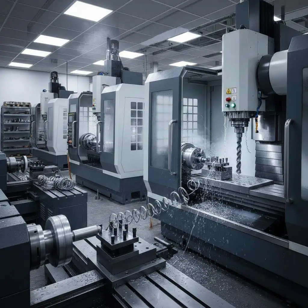
CNC Cutting Files – Start Here, Finish Faster
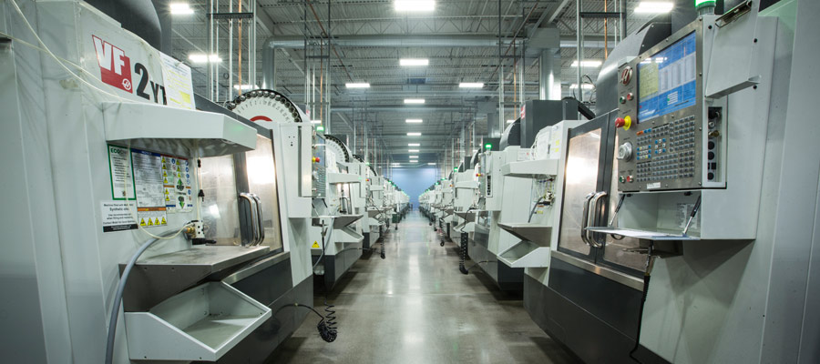
Upload your 2D/3D file to Honyo Prototype and watch it turn into a finished part in as little as 24 h. Our 3-, 4- and 5-axis CNC centres cut aluminium, steel, titanium, engineering plastics and exotics to ±0.01 mm true position, while automated in-line CMMs keep every feature on spec. From rapid prototype to 1 000-piece short run, you get an online instant quote with real-time lead time and DfM feedback the moment you hit “submit.” No waiting, no guessing—just precision metal removed at 30 000 rpm and parts in your hand on the date promised.
Technical Capabilities
As a Senior Manufacturing Engineer at Honyo Prototype, I’ll clarify upfront: “CNC cutting files” isn’t a precise technical term—it typically refers to CAD/CAM toolpath files (e.g., .nc, .gcode, .cnc) or CAD geometry files (e.g., .stp, .igs, .x_t) used to generate those toolpaths. Below are the exact technical specifications required for these files when machining tight-tolerance parts (±0.0005″ / ±0.0127mm or tighter) on 3/4/5-axis mills and lathes, with material-specific considerations for Aluminum, Steel, ABS, and Nylon.
I. Core Technical Specifications for CAD/CAM Files
(Critical for all processes)
| Parameter | Specification | Why It Matters |
|————————|———————————————————————————–|———————————————————————————–|
| CAD Geometry Format | STEP (.stp) or Parasolid (.x_t) preferred. Avoid STL for milling/turning. | STL is for additive/3D printing; it lacks surface normals and precise geometry. STEP/Parasolid preserves exact NURBS surfaces and tolerances. |
| Model Tolerance | ≤ 0.0001″ (0.0025mm) vector tolerance in CAD. All surfaces must be “water-tight” (no gaps, overlaps, or non-manifold edges). | Gaps >0.0001″ cause toolpath errors. Non-manifold geometry leads to collisions or incorrect material removal. |
| Units | Inches or Millimeters (must match machine setup). Documented in file metadata. | Unit mismatches cause 25.4x scaling errors (e.g., 1″ = 25.4mm). Industry standard is inches for US-based shops like Honyo. |
| Coordinate System | Zero point (WCS) defined at part datum (e.g., corner of stock, center of fixture). All coordinates referenced to this. | Ensures consistent part positioning. Ambiguous WCS = scrapped parts. |
| Toolpath File Format | .nc (G-code) or machine-specific format (e.g., .tnc for Heidenhain). Never submit raw .stl or .dwg for machining. | Raw CAD files require CAM programming; G-code must be validated for machine compatibility. |
II. Process-Specific Specifications
A. 3/4/5-Axis Milling
| Parameter | Specification | Material-Specific Notes |
|————————|———————————————————————————–|——————————————————————————————|
| Toolpath Strategy | Adaptive Clearing (e.g., HSMWorks) for roughing; High-Speed Machining (HSM) for finishing. 5-axis simultaneous toolpath for complex geometries (e.g., impellers, aerospace brackets). | Aluminum: High feed rates (500–1500 IPM), 80–90% stepover.
Steel: 30–80% stepover, slower feed (100–400 IPM), chip-breaker tools.
ABS/Nylon: Low feed (50–150 IPM), minimal stepdown (0.005″–0.01″) to avoid melting. |
| Tolerance Settings | Toolpath tolerance: ≤ 0.0001″ (CAM software setting). Surface finish tolerance: ≤ 0.0002″ Ra for critical features. | Tighter tolerances require smaller stepover (e.g., 0.002″ for ±0.0005″ parts). ABS/Nylon needs finer stepover due to chip adhesion. |
| Lead-In/Lead-Out | Tangential entry/exit only (no abrupt changes). Minimum 0.02″ arc radius for tool transitions. | Prevents tool deflection marks on tight-tolerance surfaces (e.g., bearing seats, precision slots). |
| 5-Axis Specifics | Tool axis control: “Point to point” or “Constant normal” for complex contours. Collision avoidance: Enabled in CAM with 0.1″ clearance buffer. | Critical for aerospace parts (e.g., turbine blades). Misconfigured axes cause gouging or machine crashes. |
B. Turning (Lathe)
| Parameter | Specification | Material-Specific Notes |
|————————|———————————————————————————–|——————————————————————————————|
| Toolpath Strategy | Constant surface speed (CSS) for finish passes. G71/G70 cycles for roughing. Thread cutting: Single-point tool with 0.0005″ depth per pass. | Steel: High rigidity, coolant flood.
Aluminum: High RPM (2000–4000 RPM), minimal chip load.
ABS/Nylon: Low RPM (500–1000 RPM), no coolant (prevents warpage). |
| Tolerance Settings | Diameter tolerance: ±0.0002″ for critical features (e.g., shaft journals). Roundness: ≤ 0.0001″. | Steel requires thermal compensation; aluminum needs thermal expansion allowances. ABS/Nylon requires low vibration to avoid chatter marks. |
| Chamfers/Deburring | All edges chamfered ≥ 0.010″ or specified radius. No sharp corners in toolpaths. | Prevents part damage during handling (critical for aerospace/medical parts). |
III. Material-Specific Requirements
| Material | Key Machining Constraints | File-Specific Adjustments |
|————–|———————————————————————————————–|———————————————————————————————-|
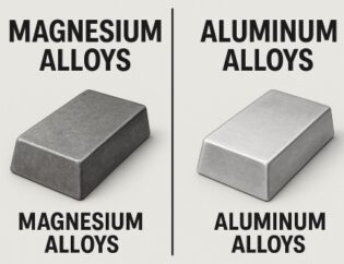
| Aluminum | – High thermal conductivity → rapid heat buildup.
– Soft, gummy → chip evacuation critical. | – Toolpath: High feed rates, large stepover (up to 80%).
– G-code: Mandatory coolant commands (M8/M9).
– Tolerance: Allow 0.0003″ thermal expansion in fixturing. |
| Steel | – Hard, abrasive → tool wear sensitive.
– High rigidity required. | – Toolpath: Low stepover (30–50%), slower feeds.
– G-code: High-pressure coolant (M7) for chip control.
– Tolerance: Use tool wear compensation offsets in G-code. |
| ABS | – Low melting point (105°C) → heat-sensitive.
– Prone to warping/vibration. | – Toolpath: Very low feed rates (<150 IPM), small stepdowns (0.005″).
– G-code: No coolant (use air blast only).
– Tolerance: Max 0.001″ total material removal per pass. |
| Nylon | – High thermal expansion (5x steel).
– Sticky chips → tool clogging. | – Toolpath: Dry machining only, sharp tools (uncoated carbide).
– G-code: Accelerate/decelerate settings reduced by 50%.
– Tolerance: Allow 0.002″ per inch for thermal growth. |
IV. Critical “Must-Haves” for Tight Tolerance (±0.0005″ or Better)
- Geometry Validation:
- All CAD surfaces must be analyzed for “deviation from nominal” (e.g., in Siemens NX or Mastercam). Max deviation ≤ 0.0001″.
- Post-Processor Settings:
- Machine-specific G-code post-processor (e.g., Haas, DMG Mori, Mazak). Generic posts cause errors in axis interpolation.
- G-code precision: 4 decimal places (e.g., X0.1234).
- Fixture Integration:
- CAD must include fixture geometry (e.g., vises, chucks) to avoid collisions.
- Toolpath Simulation:
- Full 3D simulation (e.g., in CAM software) to verify no gouges, collisions, or overcuts.
💡 Honyo Prototype Standard Practice: For aerospace/medical parts, we require:
– STEP files with ISO 10303-21 metadata.
– G-code with NIST-compliant syntax (no proprietary codes).
– Dimensional reports (CMM measurements) tied to CAD datums.
– Material certification (e.g., AMS 4037 for aluminum, ASTM F663 for nylon) in the file package.
V. Common Pitfalls to Avoid
- ❌ Using STL files for milling/turning → Surface mesh errors cause scalloping.
- ❌ Ignoring tool radius compensation (G41/G42) → Parts out of tolerance by tool diameter.
- ❌ Overlooking thermal effects in plastics → ABS warps if cut too fast; nylon absorbs moisture (pre-dry to <0.2% moisture).
- ❌ No toolpath simulation → 30% of scrapped parts stem from undetected collisions.
Conclusion
For tight-tolerance CNC machining, file specs must be engineered for the machine, material, and tolerance—not just “exported from CAD.” At Honyo, we enforce these standards to ensure first-time-right production. Always validate files with:
1. CAD geometry checks (no gaps, clean topology),
2. CAM toolpath simulation (no collisions),
3. G-code review for machine-specific quirks (e.g., Haas vs. DMG Mori).
Need a file review? Share your CAD/CAM data (STEP + toolpath settings), and we’ll provide a free tolerance feasibility report. 🛠️
From CAD to Part: The Process
Honyo Prototype “CNC cutting-file” workflow
(what happens to your CAD from the moment it lands on our server until the finished parts reach your dock)
-
Upload CAD
• Portal accepts any mix of STEP, IGES, XT, SLDPRT, CATPart, Fusion, Inventor, etc.
• 2-D drawings (PDF, DWG, DXF) are auto-linked to the 3-D model.
• Built-in repair engine closes gaps, deletes duplicate faces, heals small overlaps—so the machinist starts with a watertight solid, not a “dirty” IGES.
• Instant checksum e-mails you a receipt with a Honyo job number; the file is AES-encrypted at rest. -
AI Quote (≤5 min)
• Geometry classifier decides: 3-axis, 3+2, full 5-axis, or turn-mill.
• Feature extractor counts holes, pockets, ribs, undercuts, deepest slot, smallest radius, largest tool reach, estimated cycle time per setup.
• Stock calculator chooses the cheapest plate or round bar from our Shenzhen & Suzhou inventory (aluminum 6061-T6, 7075-T6, 316L, Ti-6Al-4V, Delrin, PEEK, etc.).
• Real-time machine-loading algorithm looks at 210 CNC mills/lathes and 12 palletized 5-axis cells, then prices the open windows.
• Dynamic routing: if tolerance ≤ ±0.01 mm or Ra ≤ 0.4 µm is requested, quote automatically adds grinding/precision lapping step.
• You receive an interactive quote: unit price, batch price curve, 3 lead-time options (24 h, 3-day, 7-day economy), and a 360° cost-driver breakdown you can click to modify (material, finish, quantity, tolerance).
• Click “Accept” → file locks and moves to DFM. -
DFM (Design-for-Manufacturing)
• Hybrid review: AI flags impossible tolerances, deep rib chatter risk, cutter collision zones; human senior machinist confirms within 30 min.
• Automatic suggestion sheet:
– Increase internal corner radius from 0.3 mm to 0.5 mm → saves 18 min machine time.
– Add 0.5° draft on tall thin wall → eliminates secondary EDM.
• You approve or reject each suggestion in-browser; model rev-bumps to ‑A, ‑B, etc.
• Final signed DFM triggers automatic CAM:
– Feature-based tool-path generation (Fusion 360 & hyperMILL engines).
– G-code post-processed for our Brother SPEEDIO S700X1 (3-axis) or DMG MORI DMU 65 monoBLOCK (5-axis).
– Cutting files stored in Git-style repo—every rev is traceable. -
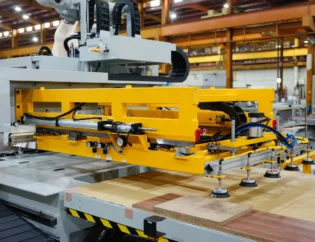
Production
a. Prep & Setup
– Bar-coded material pulled from stock; alloy certificate scanned into MES.
– Cutter kit auto-assembled: carbide end mills, diamond-coated routers, ceramic inserts picked by tool-management software; lengths measured with a Zoller to ±5 µm.
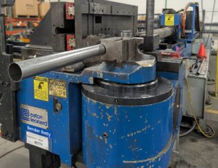
b. CNC Cutting
– First-article probing: Renishaw spindle probe maps stock offset; cutter-comp values updated automatically.
– In-cycle laser scans every 10th feature; if dimension drifts >75 % of tolerance band, tool is flagged for replacement.
– Coolant concentration, spindle load, and vibration streamed to cloud dashboard; customer link lets you watch live.
c. Post-Machining
– Deburr, ultrasonic clean, vapor-degrease.
– Optional: anodize Type II/III, chem-film, passivation, nickel-Teflon, DLC, or 1 µm Ra polishing.
d. QC & CofC
– CMM report (Hexagon GLOBAL S) + 2-D height gauge + surface finish profilometer.
– Digital CofC (PDF + raw CMM data) attached to the same job number; automatic compare against original CAD nominal. -
Delivery
• Parts vacuum-sealed with desiccant, VCI paper, and foam cut-outs CNC-routed to match part outline (no movement in transit).
• Shipping matrix:
– Asia: 8 h express courier.
– USA/EU: 48–72 h DHL/UPS priority with bonded-export clearance handled by Honyo.
• Track & trace link pushes milestone scans to your Slack/Teams if you wish.
• Box contains QR code; scan it and you see the entire digital traveler: material cert, tool list, G-code rev, inspection data, and courier carbon footprint.
Typical elapsed time from “Upload CAD” to “Delivery”
• 24 h Super-Rush (≤20 parts, Al 6061, no finish)
• 3-day Standard (most engineering prototypes)
• 7-day Economy (higher quantities or exotic alloys)
That is the full, closed-loop CNC cutting-file process we run at Honyo Prototype.
Start Your Project
Ready to bring your designs to life?
Get precise, high-quality CNC cutting files from Honyo Prototype—backed by our Shenzhen factory’s expertise in precision manufacturing.
📞 Contact Susan Leo today:
📧 info@hy-proto.com
Fast turnaround | Industry-leading accuracy | Global delivery
Your trusted partner for prototyping and production.
🚀 Rapid Prototyping Estimator