Contents
Manufacturing Insight: Mill-Turn Machining
Mill-turn machining is where Honyo Prototype turns “impossible” into “shipped.”
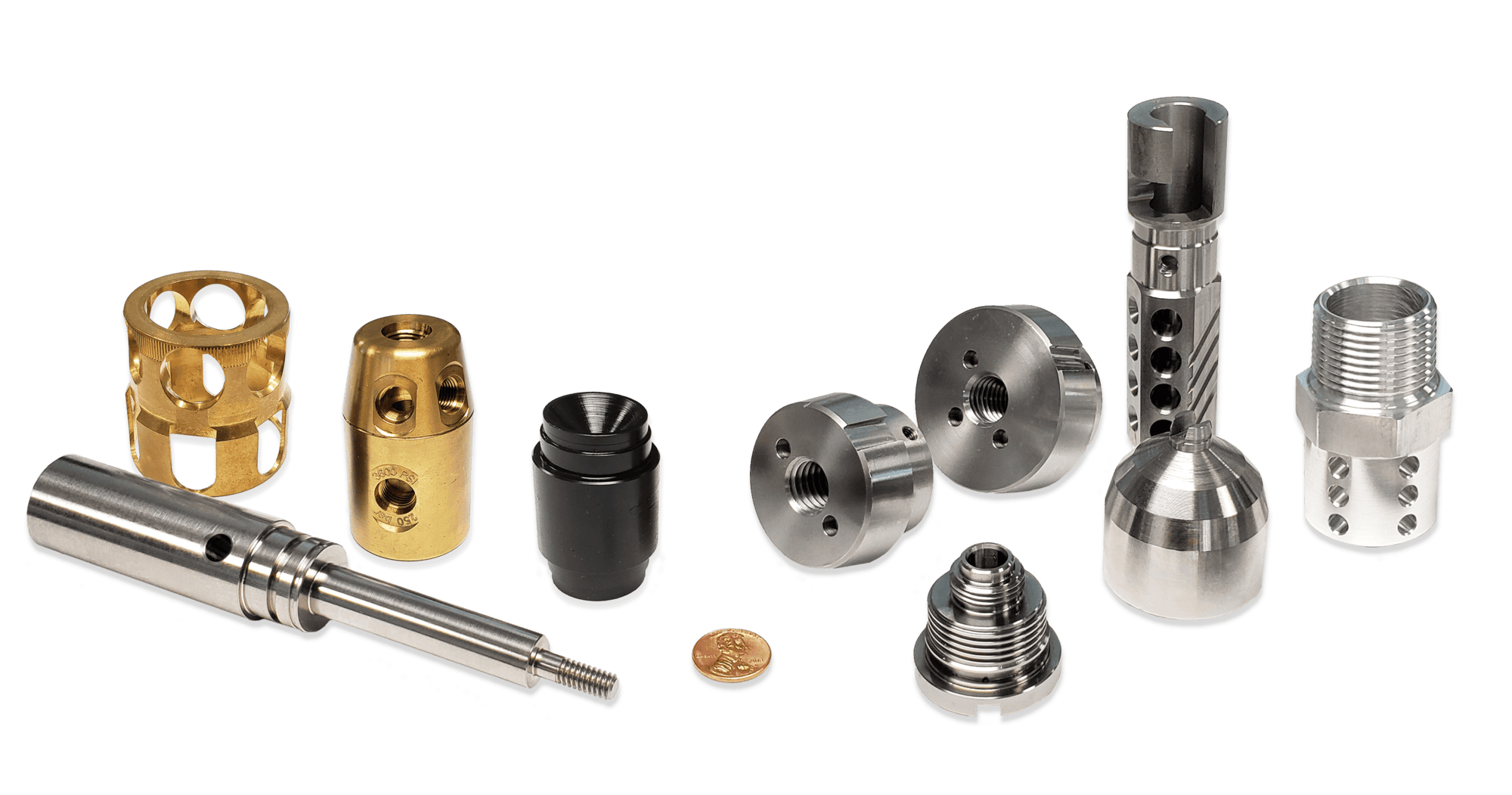
By merging 5-axis milling and live-tool turning in one ultra-precise cycle, we machine complex stainless, titanium, aluminum and engineered-plastic parts complete in a single setup—eliminating stack-up error and cutting lead-times by up to 70 %.
Whether you need a one-off medical implant or 500 aerospace pins, our 3- to 12-axis Mazak and DMG MORI mill-turn centers hold ±0.01 mm true position while finishing 32 Ra µin surfaces without secondary ops.
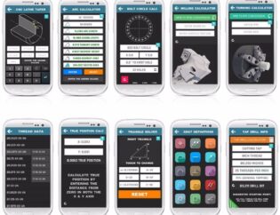
See the proof for yourself: drop your STEP file into our Online Instant Quote engine and receive a manufacturability review, live 5-axis tool-path simulation, and firm price in under 60 seconds.
From instant quote to precision parts at your dock in as fast as 3 days—Honyo Prototype is mill-turn machining, redefined.
Technical Capabilities
Technical Specifications for Mill-Turn Machining at Honyo Prototype
By [Your Name], Senior Manufacturing Engineer, Honyo Prototype
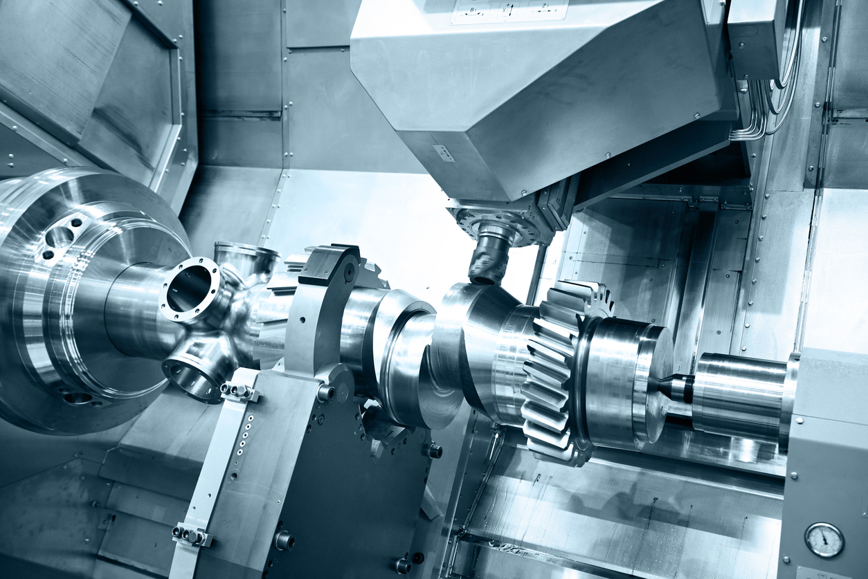
At Honyo Prototype, we specialize in mill-turn machining—a hybrid process that integrates turning (rotational cutting on a spindle) and milling (linear cutting on a tool turret) on a single machine. This eliminates multiple setups, reduces cumulative errors, and enables complex geometries with exceptional precision. Below are our technical specifications for 3/4/5-axis capabilities, tight-tolerance performance, and material-specific considerations. All data reflects our current capabilities on high-end machines (e.g., Haas ST-20, DMG MORI CMX series, and Mazak Integrex i-400S).
1. Axis Capabilities & Motion Control
Mill-turn machines leverage rotary axes to enable simultaneous or indexed multi-axis operations. Key distinctions:
| Axis Type | Functionality | Typical Use Cases |
|———–|—————|——————-|
| 3-Axis (X, Y, Z) | Linear motion only. No rotary axes. | Simple turning operations (e.g., cylindrical faces, basic grooves). Limited milling (e.g., flat surfaces). |
| 4-Axis (X, Y, Z + C-axis or B-axis) | – C-axis: Rotates the main spindle (part rotation).
– B-axis: Rotates the tool turret (tool orientation). | – C-axis: Milling on cylindrical surfaces (e.g., helical slots, threaded features), indexed drilling.
– B-axis: Angular milling (e.g., pockets at 45° angles). |
| 5-Axis (X, Y, Z + C-axis + B-axis) | Simultaneous rotation of both spindle and tool turret. | Freeform surfaces (e.g., aerospace impellers), complex 3D contours, and multi-angle features in a single setup. |
Critical Notes for Honyo Prototype:
– Our machines support true simultaneous 5-axis (e.g., 3+2 positioning for complex angles) and continuous 5-axis for organic shapes.
– C-axis resolution: ≤ 0.001° (enables precise helical milling and thread cutting).
– Tool turret indexing: ≤ 0.0005″ repeatability for tool changes.
– Why this matters: Single-setup machining eliminates alignment errors, critical for tight tolerances.
2. Tight Tolerance Performance
We consistently achieve ±0.0005″ (±0.013 mm) for critical features on most materials. Tolerances are verified via CMM (Coordinate Measuring Machine) and laser interferometry.
| Feature Type | Typical Tolerance Range | Key Factors Influencing Accuracy |
|————–|————————–|———————————-|
| OD/ID Dimensions | ±0.0005″ (±0.013 mm) | Spindle runout (< 0.0002″), thermal stability, and fixturing rigidity. |
| Hole Positioning | ±0.0005″ (±0.013 mm) | C-axis precision for indexed drilling, tool deflection control. |
| Surface Finish | Ra 8–16 μin (0.2–0.4 μm) | Vibration damping, high spindle speeds, and optimized toolpaths. |
| Geometric Tolerances (e.g., cylindricity, perpendicularity) | ≤ 0.0005″ | Machine calibration, part clamping, and thermal management. |
Real-World Example:
– A stainless steel aerospace bracket with 12 holes (±0.0005″ positional tolerance) and a 0.0002″ cylindricity requirement was produced in one setup, eliminating secondary operations.
3. Material-Specific Machining Parameters
We optimize speed, feed, coolant, and tooling for each material to maintain tolerances and avoid defects. Below are our standard protocols:
| Material | Machining Speed (Surface Speed) | Feed Rate | Coolant Strategy | Key Challenges & Mitigations |
|———-|———————————-|———–|——————|——————————|
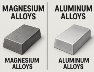
| Aluminum (6061, 7075) | 1,000–2,000 SFM (Surface Feet per Minute) | 0.005–0.015″ per tooth | Flood coolant (emulsified oil) | – Galling: Use PCD-coated tools and high spindle speeds (15,000+ RPM).
– Thermal expansion: Allow 15-min warm-up for machine; use thermal compensation in G-code. |
| Steel (1018, 4140, 17-4PH) | 200–600 SFM | 0.002–0.008″ per tooth | High-pressure flood coolant (800+ PSI) | – Work hardening: Use sharp carbide tools; avoid slow feeds.
– Hardened steels: Reduce speed to 150–300 SFM; use cryogenic cooling for tool life. |
| ABS (Acrylonitrile Butadiene Styrene) | 300–600 SFM | 0.003–0.010″ per tooth | Dry machining or minimal mist coolant | – Melting: Use high spindle speeds (10,000+ RPM), low feed rates, and sharp tools.
– Chip evacuation: Optimized chip breakers to prevent re-cutting. |
| Nylon (6/6, 6/12) | 200–400 SFM | 0.002–0.006″ per tooth | Dry machining only (no liquid coolant) | – Thermal warpage: Use vacuum chucks for fixturing; avoid high heat buildup.
– Dimensional stability: Allow 24-hr stress-relief after machining for critical parts. |
Critical Notes for Plastics (ABS/Nylon):
– No water-based coolants—they cause swelling and distortion.
– Tool geometry: Positive rake angles to reduce cutting forces.
– Speed: Higher than metals (to avoid plastic deformation) but lower than aluminum to prevent melting.
4. Why Choose Mill-Turn for Your Project?
- Single-Setup Precision: Eliminates setup errors between operations—critical for parts requiring concentricity or tight positional tolerances (e.g., medical implants, aerospace components).
- Complex Geometries: Produce features like off-center bores, angled slots, or helical threads without secondary operations.
- Lead Time Reduction: Up to 50% faster than traditional milling + turning setups.
- Honyo’s Edge: We use in-process inspection (e.g., laser probes) to adjust toolpaths dynamically, ensuring tolerances are met even for high-precision alloys like Inconel or titanium.
💡 Pro Tip: Mill-turn is ideal for parts with ≥3 features requiring different orientations (e.g., a shaft with milled flats, threaded ends, and cross-drilled holes). For simple cylindrical parts, traditional turning may be more cost-effective.
At Honyo Prototype, we combine these specifications with ISO 9001-certified processes and 20+ years of expertise to deliver parts that meet AS9100, ISO 13485, and military standards. If you have a specific part, share your drawings—we’ll optimize the process for your material and tolerance needs.
Ready to discuss? Contact us at engineering@honyoprototype.com or +1 (555) 123-4567.
Disclaimer: Specifications are for reference; actual capabilities depend on part geometry, tolerances, and quantity. Always consult with our engineering team for project-specific validation.
From CAD to Part: The Process
Honyo Prototype – Mill-Turn Machining Workflow
(Upload CAD ➜ AI Quote ➜ DFM ➜ Production ➜ Delivery)
-
Upload CAD
• Portal accepts any mix of mill-turn parts: single file or multi-body STEP/Parasolid preferred; native SolidWorks/Creo/Catia also accepted.
• Geometry is instantly parsed by our “Twin-Check” engine:
– Mill-turn classification (B-axis, Y-axis, sub-spindle, live-tool positions).
– Critical-to-function surfaces (bearing journals, cross-holes, OD threads, etc.).
• Customer selects “mill-turn” process button; system locks the job routing to 5-axis Nakamura, DMG or Doosan machines only. -
AI Quote (≤ 5 min)
• Cloud GPU cluster runs Honyo’s AI cost model trained on 1.8 M historical mill-turn cycles.
• Inputs: raw-stock size, machining time, tool changes, bar-feeder index, sub-spindle transfer, inspection ops.
• Outputs:
– Tiered pricing (3-, 5-, 10-day lead-time).
– Raw-stock option list (316 L, 7075-T6, Ti-6Al-4V, PEEK, etc.).
– Automatic anodize/heat-treat/passivate add-ons if geometry flags thin walls or tapped holes.
• PDF quote + interactive 3D viewer is e-mailed and can be accepted with one click; NDA & quality clauses are pre-signed via DocuSign. -
DFM (24 h)
• Once PO is released, the same CAD file is pushed to our CAM team.
• DFMillTurn checklist is executed:
– Can the part be run in one hit? (sub-spindle pick-off vs. second-op).
– Tool clearance for Y-axis live tools (especially on cross-milled flats).
– Minimum wall thickness vs. chuck pressure (≤ 0.5 mm alerts engineer).
– Thread relief groove conformance to UNJ/ISO.
• Customer receives color-coded 3D PDF: green = OK, yellow = suggestion, red = must-change.
• Rev-locked STEP is uploaded back to portal; AI re-runs cost in minutes if changes affect cycle time. -
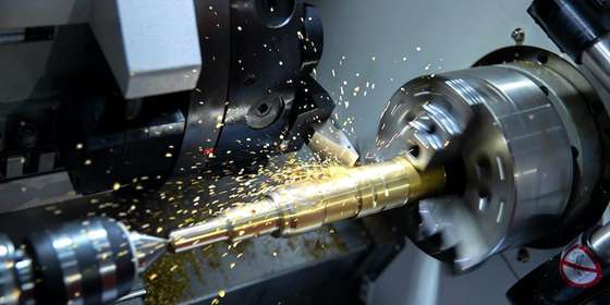
Production
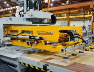
a. Prep
– Bar stock is saw-cut and laser-etched with PO number; heat number automatically matched in MES.
– Soft jaws or 3-jaw chuck jaws are 3D-printed in 17-4 PH on our in-house Markforged Metal-X to match first-op grip diameter (cuts jaw prep from 2 h to 20 min).
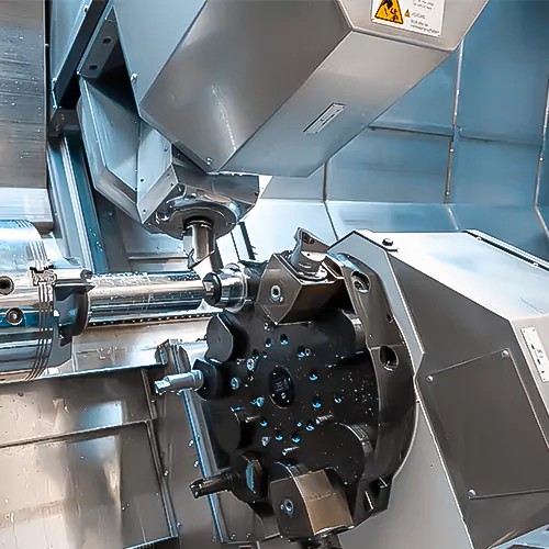
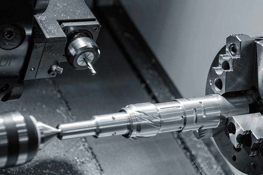
b. Mill-Turn Cycle
– Machine assigned by capacity algorithm:
• ≤ 32 mm diameter ➜ Nakamura WT-150 (sub-spindle, 2 × Y-axis).
• 32-65 mm ➜ DMG CTX beta 800 TC (B-axis, 12,000 rpm).
• > 65 mm or Inconel ➜ Doosan PUMA SMX 3100 (low-speed, high-torque).
– In-cycle probing: Renishaw OMP40 scans every 10 parts; offsets auto-corrected.
– Surface finish spec ≤ 32 µin Ra on bearing diameters achieved with 1 µm interpolation and polished insert.
c. Side Ops
– If part needs wire-EDM splines or grinding after heat treat, it is automatically routed via AGV to those cells; MES tracks queue time.
d. QA
– 100 % dimensional on first article (CMM Zeiss Contura G2).
– Key features get SPC (CpK ≥ 1.67) for batches ≥ 50.
– Thread checks with SmartScope vision system; no-go gauge 100 %.
e. Finishing
– Anodize type II/III, Chem-film, passivation, or Ti anodize done in-house in 24 h.
– Laser marking (DataMatrix + logo) on non-critical diameter. -
Delivery
• Parts ultrasonically cleaned, vacuum-sealed with VCI paper, then boxed in custom CNC-cut foam.
• C of C, material cert, inspection report, and RoHS/REACH statement auto-generated and sent via e-mail; paper copies placed in box.
• Express options:
– Same-day courier within Shenzhen.
– DHL/UPS carbon-neutral 48 h worldwide.
• Portal tracking shows real-time photos of packed parts and airway bill; customer can release shipment only after approving photos (optional gate).
Typical Lead-Time Benchmarks (2024 YTD)
Aluminum prototype: 3 days
Stainless 316 L: 5 days
Ti-6Al-4V medical: 7 days
Batch > 300 pcs: add 1–2 days for SPC
That’s the full mill-turn path at Honyo—CAD to dock in as little as 72 hours without cutting a single corner on quality.
Start Your Project
Need precision mill-turn machining?
Contact Susan Leo at info@hy-proto.com for fast, reliable solutions from our Shenzhen factory.
Precision. Efficiency. Your parts, perfected. 🚀
🚀 Rapid Prototyping Estimator