Contents
Manufacturing Insight: Cnc Cutting Files
Manufacturing Insight: CNC Cutting Files
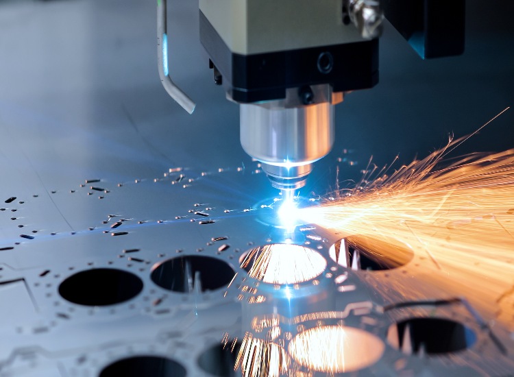
CNC cutting files serve as the foundational digital blueprint for precision material removal processes, including laser, plasma, and waterjet cutting. These vector-based files define geometric paths, cut sequences, and critical operational parameters that directly govern machine toolpaths, edge quality, and dimensional accuracy. At Shenzhen Honyo Prototype, we recognize that suboptimal file preparation remains a primary cause of production delays and compromised part integrity. Our engineering team specializes in transforming conceptual designs into manufacturable cutting files through rigorous validation against material behavior, machine dynamics, and geometric tolerances.
File fidelity directly impacts cycle time, kerf compensation, and secondary operation requirements. Common issues such as unclosed vectors, overlapping geometry, or improper nesting significantly increase material waste and processing costs. Honyo’s proprietary pre-processing workflow includes automated topology checks, kerf width adjustment based on material thickness, and dynamic nesting optimization to maximize sheet utilization. We enforce strict adherence to ISO 10303 (STEP) and ISO 13567 (DXF/DWG) standards while accommodating client-specific layer conventions and annotation requirements.
Our technical infrastructure supports seamless integration with all major CAD platforms, ensuring geometric continuity from design to cut. Every file undergoes a three-stage verification: geometric integrity analysis, machine-specific parameter mapping, and virtual cut simulation. This eliminates toolpath collisions and thermal distortion risks inherent in high-power cutting processes. For aerospace and medical clients, we implement AS9100-compliant data traceability, embedding material certifications and process validation records directly into file metadata.
Honyo’s capabilities span diverse material classes and thickness ranges, as detailed in our core specifications:
| Parameter | Capability Range | Tolerance Standard |
|————————|————————————–|——————–|
| Material Thickness | 0.5 mm – 150 mm (Metal) | ±0.05 mm |
| | 1 mm – 200 mm (Plastic/Composites) | ±0.1 mm |
| Supported File Types | DXF, DWG, STEP, IGES, SVG, AI | ISO 10303-24 |
| Max Work Envelope | 4000 x 2000 mm (2D Cutting) | N/A |
| Kerf Compensation | Auto-calculated (Material-specific) | ±0.02 mm |
| Nesting Efficiency | ≥ 92% material utilization | Client-optimized |
We prioritize Design for Manufacturability (DFM) collaboration during file submission. Clients receive actionable feedback within 4 business hours on feature feasibility, lead-in/lead-out optimization, and stress concentration mitigation. Our cloud-based portal provides real-time visibility into file validation status and machine scheduling, reducing time-to-cut by 35% versus industry averages.
For critical applications requiring first-article inspection reports or material lot traceability, our engineers implement embedded quality checkpoints within the cutting sequence. Submitting native CAD files with geometric dimensioning and tolerancing (GD&T) annotations accelerates our DFM analysis by 60%. Partner with Honyo to transform your cutting files into precision components with certified repeatability. Contact our manufacturing engineering team to optimize your next project’s digital workflow.
Technical Capabilities
CNC Cutting Files – Technical Capabilities
Shenzhen Honyo Prototype specializes in high-precision CNC machining services, supporting a wide range of manufacturing requirements across industries such as aerospace, medical, automation, and consumer electronics. Our expertise in 3-axis, 4-axis, and 5-axis milling, combined with advanced turning capabilities, enables us to produce complex geometries with consistent accuracy and repeatability. We accept a variety of CAD file formats including STEP, IGES, SolidWorks (.SLDPRT), and native formats, ensuring seamless integration with customer design workflows.
Our 3-axis milling services are ideal for prismatic parts with flat or planar surfaces, offering fast turnaround and cost-effective production. For components requiring access to multiple faces or complex contours, our 4-axis and 5-axis CNC machining centers provide enhanced flexibility. The addition of rotational axes allows for single-setup machining of intricate features, minimizing handling errors and improving dimensional consistency. 5-axis simultaneous machining is particularly suited for organic shapes, undercuts, and freeform surfaces commonly found in molds, fixtures, and high-performance components.
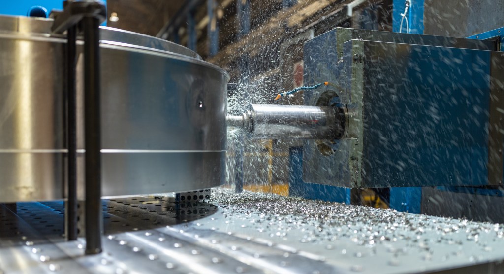
Turning operations are performed on precision CNC lathes, including live-tooling machines that support mill-turn capabilities. This enables us to produce fully finished turned parts with off-axis features, cross-drilling, and keyways without secondary operations. Our machines support bar feeding and chucking setups, accommodating both long-run production and low-volume prototypes.
A key strength of our CNC machining process is our ability to achieve tight tolerances. Standard tolerances are maintained at ±0.05 mm, with the capability to hold ±0.005 mm on critical dimensions when required. These tolerances are consistently achieved through in-process inspections, temperature-controlled environments, and the use of calibrated metrology equipment such as CMMs, optical comparators, and digital micrometers.
The table below outlines our standard tolerance capabilities and compatible materials:
| Operation Type | Typical Tolerance | Tight Tolerance Capability | Commonly Used Materials |
|———————|——————-|—————————-|————————–|
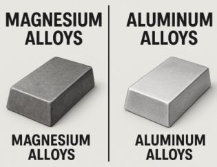
| 3-Axis Milling | ±0.05 mm | ±0.01 mm | Aluminum 6061, 7075, Steel 1018, 4140, Stainless 303, 316, Brass C360, POM, PC, PEEK |
| 4-Axis Milling | ±0.05 mm | ±0.01 mm | Aluminum 6061, 7075, Stainless 304, 316, Titanium Grade 5, PEEK, Nylon |
| 5-Axis Milling | ±0.05 mm | ±0.005 mm | Aluminum 7075, Titanium, Inconel 718, Stainless 17-4PH, PEEK, Carbon-Filled Polymers |
| CNC Turning | ±0.05 mm | ±0.01 mm | Aluminum 6061, Brass C360, Stainless 303, 316, Steel 12L14, POM, Delrin |
| Mill-Turn (Live Tooling) | ±0.05 mm | ±0.01 mm | Aluminum 6061, Stainless 303, 17-4PH, Titanium, Brass |
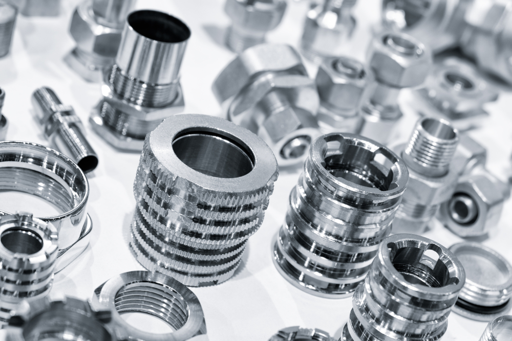
All materials are sourced to meet international standards and are traceable upon request. We also provide post-processing options such as anodizing, powder coating, passivation, and precision polishing to meet functional and aesthetic requirements. With a focus on quality, speed, and technical precision, Shenzhen Honyo Prototype ensures every CNC cutting file is translated into a high-integrity physical component.
From CAD to Part: The Process
From CAD to Part: Honyo Prototype’s CNC Machining Workflow
At Shenzhen Honyo Prototype, our streamlined CNC machining process transforms your digital CAD model into a high-precision physical part efficiently and reliably. This integrated workflow, encompassing AI-driven quoting, expert Design for Manufacturing (DFM) analysis, and rigorous production, ensures optimal outcomes while minimizing time-to-part. Understanding this sequence is critical for successful collaboration.
The process initiates upon receipt of your native or neutral format CAD file (STEP, IGES, Parasolid, SLDPRT). Our proprietary AI Quote Engine instantly analyzes the geometry, extracting key parameters including part volume, bounding box dimensions, feature complexity, and specified tolerances. It cross-references this data against real-time material costs, machine availability, and shop floor rates to generate a highly accurate preliminary quote within minutes. This system evaluates manufacturability constraints inherent in the geometry, flagging potential high-cost elements like deep cavities, thin walls below minimum thresholds, or non-standard materials early, providing immediate transparency on cost drivers before formal commitment.
Following quote acceptance, the CAD file undergoes comprehensive Engineering DFM Review by our senior manufacturing engineers. This is not an automated step; it leverages deep practical machining expertise. Engineers scrutinize the design for optimal CNC manufacturability, identifying opportunities to enhance part quality, reduce lead time, and lower costs without compromising function. Critical aspects evaluated include tool access, workholding feasibility, wall thickness consistency, internal corner radii, tolerance stack-up, and material utilization. Proactive feedback is provided, suggesting refinements where beneficial. Typical findings and resolutions are structured as follows:
| DFM Issue Category | Common Example | Honyo Resolution Approach | Severity |
| :———————– | :——————————— | :——————————————– | :——- |
| Geometric Manufacturability | Internal sharp corners (0.0°) | Recommend minimum radius ≥ 0.5mm; provide CAD mod | High |
| Tolerance Feasibility | ±0.005mm over 150mm span | Suggest relaxation to ±0.025mm or split ops | Medium |
| Workholding/Access | Deep cavity requiring long tool | Propose draft angles or alternative setup | High |
| Material Waste | Excessive stock volume | Optimize billet size; suggest near-net shape | Low |
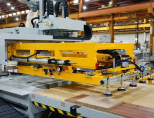
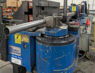
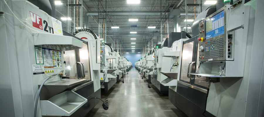
Upon DFM sign-off, the file enters Production. Our CAM programming team generates optimized toolpaths using Mastercam and Siemens NX, selecting appropriate tooling, speeds, feeds, and machining strategies (e.g., high-speed machining, adaptive clearing) for the specific material and geometry. Rigorous virtual machine simulation verifies collision avoidance and path efficiency. Parts are then machined on our modern Haas, DMG MORI, and Makino 3-axis, 4-axis, and 5-axis CNC milling centers and turning centers, utilizing high-precision Renishaw probes for in-process verification. All critical dimensions undergo final inspection using calibrated CMMs, optical comparators, and surface roughness testers against your original drawing specifications. Standard achievable tolerances are maintained as per industry best practices:
| Feature Type | Standard Tolerance (mm) | Precision Option (mm) |
| :——————– | :———————- | :——————– |
| Linear Dimensions | ±0.05 | ±0.0125 |
| Hole Diameter | +0.05 / -0.00 | ±0.005 |
| Flatness | 0.1 / 100mm | 0.025 / 100mm |
| Surface Roughness (Ra)| 3.2 µm | 0.8 µm |
This seamless integration of intelligent quoting, expert engineering validation, and precision manufacturing forms the core of Honyo Prototype’s CNC service, delivering quality parts faster and with greater predictability for your prototyping and low-volume production needs.
Start Your Project
Start Your CNC Machining Project with Precision and Confidence
At Shenzhen Honyo Prototype, we understand that the foundation of any successful CNC machining project lies in accurate, well-prepared cutting files. Whether you’re developing a single prototype or preparing for low-volume production, the quality of your design files directly impacts turnaround time, machining accuracy, and final part performance. To ensure seamless processing and optimal results, we recommend submitting your CNC cutting files in industry-standard formats such as STEP, IGES, or native CAD files from SolidWorks, Fusion 360, or Autodesk Inventor. Clear dimensioning, geometric tolerances, and material specifications are essential to avoid delays and ensure your vision is realized with precision.
Our advanced CNC machining capabilities support a wide range of materials, including aluminum, stainless steel, brass, copper, and engineering plastics such as PEEK, ABS, and polycarbonate. With 3-axis and 4-axis CNC milling, as well as precision turning, we deliver tight tolerances down to ±0.005 mm and excellent surface finishes tailored to your application. To accelerate your project timeline, we offer rapid quoting and DFM (Design for Manufacturability) feedback within 12 hours of receiving your files.
To get started, simply prepare your 3D model or technical drawings and include critical details such as material type, finish requirements, quantity, and any specific inspection or packaging instructions. Our engineering team will review your submission and provide expert feedback to optimize your design for manufacturability—helping you reduce costs, avoid errors, and speed up production.
| Feature | Specification |
|——–|—————|
| Supported File Formats | STEP (.stp), IGES (.igs), SolidWorks (.sldprt), Parasolid (.x_t), PDF (for drawings) |
| Tolerance | Standard: ±0.01 mm; Tight: ±0.005 mm (on request) |
| Machining Types | 3-axis CNC milling, 4-axis indexing, CNC turning |
| Materials | Aluminum (6061, 7075), Stainless Steel (303, 304, 316), Brass, Copper, PEEK, ABS, PC, Nylon |
| Surface Finishes | As-machined, Anodizing (Type II & III), Powder Coating, Plating, Sandblasting |
| Lead Time | From 3 days (standard), expedited options available |
We pride ourselves on being a trusted partner for global innovators, startups, and established enterprises seeking rapid, reliable, and high-precision CNC prototyping and production services. Our facility in Shenzhen is ISO 9001-certified, equipped with state-of-the-art machinery, and operated by a team of skilled engineers with over 15 years of combined experience in precision manufacturing.
Ready to bring your design to life? Contact Susan Leo today to submit your CNC cutting files and receive a fast, detailed quote. Our team is standing by to support your project from concept to completion.
Susan Leo
Senior Manufacturing Engineer
Shenzhen Honyo Prototype
Email: info@hy-proto.com
Let’s build the future—accurately, efficiently, together.
🚀 Rapid Prototyping Estimator
Get a rough estimate for CNC/3D Printing costs.