Contents
Manufacturing Insight: Injection Mold Parting Line
Manufacturing Insight: Injection Mold Parting Line Fundamentals and Execution
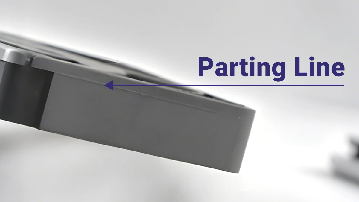
The parting line in injection molding represents the critical interface where the two primary mold halves—the cavity and core—converge during closure. This seam directly dictates the final part’s dimensional integrity, surface quality, and functional performance. Precisely managing the parting line is non-negotiable; deviations cause flash, sink marks, or mismatched geometry, leading to assembly failures or aesthetic rejection. At Shenzhen Honyo Prototype, we treat parting line optimization as foundational to rapid tooling success, integrating it from initial CAD design through mold validation.
Poorly executed parting lines introduce costly downstream issues. Excessive clamp force may suppress flash but accelerates mold wear, while inadequate draft angles or misaligned ejector pins exacerbate part ejection stress. Complex geometries—such as deep undercuts or thin-walled features—demand strategic parting line placement to avoid weak knit lines or trapped air. Honyo’s engineering team leverages mold flow simulation and DFM analysis early in the process to predict and eliminate these risks. Our rapid tooling protocols ensure cavity-core alignment tolerances remain within ±0.02 mm, minimizing post-mold machining and accelerating time-to-part.
Honyo’s precision parting line execution stems from proprietary CNC machining workflows and real-time process monitoring. We utilize hardened P20 or H13 steel molds with mirror-polished shut-off surfaces, reducing flash formation even in high-viscosity engineering resins. Each mold undergoes rigorous bench testing for parallelism and venting efficiency before production. For complex multi-cavity tools, our modular insert system maintains consistent parting line integrity across all cavities, ensuring batch uniformity. This disciplined approach allows us to deliver Class A surface finishes on visible edges and zero-flash critical sealing surfaces—key requirements for medical, automotive, and consumer electronics clients.
Our rapid tooling capabilities translate parting line precision into tangible client advantages: reduced scrap rates, elimination of secondary de-flashing operations, and compliance with stringent ISO 2768-mK geometric tolerances. Below outlines Honyo’s standard parting line performance metrics for production-grade aluminum and steel molds.
| Parameter | Aluminum Rapid Tooling | Steel Production Tooling | Measurement Standard |
|————————–|————————|————————–|———————-|
| Parting Line Tolerance | ±0.03 mm | ±0.02 mm | ISO 2768 |
| Surface Finish (Shut-off)| Ra 0.4 µm | Ra 0.2 µm | ISO 1302 |
| Flash Limit (Typical) | ≤ 0.05 mm | ≤ 0.03 mm | ASTM D3641 |
| Max Cavity Count | 8 | 32 | Client-Specific |
| Material Compatibility | ABS, PC, PP, PA6 | All thermoplastics incl. PEEK, LCP | UL/ISO Certified |
Honyo Prototype’s mastery of parting line dynamics ensures your functional and aesthetic requirements are met without iterative mold corrections. By embedding precision engineering into rapid tooling workflows, we deliver injection-molded parts that perform to specification—on time and at scale. Partner with us to transform complex geometries into flawless production realities.
Technical Capabilities
Injection Mold Parting Line Specifications at Shenzhen Honyo Prototype
At Shenzhen Honyo Prototype, precision in parting line execution is central to our rapid tooling and injection molding capabilities. The parting line—the interface where the two mold halves meet—directly impacts part aesthetics, dimensional accuracy, and functional performance. Our engineering team ensures tight control over parting line definition across both steel and aluminum molds, enabling clean part separation, minimal flash, and consistent repeatability from T1 samples through production.
We specialize in prototype and bridge tooling using high-grade aluminum (7075-T6, 6061-T6) and tool steel (P20, H13, 420 stainless) molds, each selected based on project requirements for volume, material, and surface finish. Our in-house CNC machining, wire EDM, and surface grinding processes ensure parting line alignment within tight tolerances, even on complex geometries with undercuts and side-actions. Mold base components are precision-fitted, and cavity/core inserts are aligned using hardened guide pins and bushings to maintain long-term stability.
A key differentiator at Honyo is our ability to deliver T1 samples in as little as 7 days without sacrificing parting line integrity. This rapid turnaround is enabled by our integrated design-for-manufacturability (DFM) review, concurrent mold fabrication, and real-time quality verification. During mold validation, we conduct a full parting line inspection using optical comparators and coordinate measuring machines (CMM) to verify alignment, step-off, and flash potential.
Our process accounts for material behavior during injection, including thermal expansion and clamp force distribution, to optimize parting line seal and venting. For cosmetic parts, we apply fine EDM texturing or polished finishes across the parting interface to minimize visible witness lines. For functional components, we utilize precision shut-offs and seal ribs to prevent flash in critical sealing zones.
All molds undergo a first-article trial run, where T1 parts are evaluated for parting line consistency, dimensional conformity, and surface quality. Adjustments are implemented in real time to ensure the final mold meets all technical and aesthetic criteria prior to customer approval.
The following table outlines our standard capabilities and tolerances related to parting line control and mold construction:
| Parameter | Aluminum Molds | Steel Molds | Notes |
|——————————-|——————————|——————————|—————————————-|
| Parting Line Alignment | ±0.02 mm | ±0.01 mm | Measured at cavity/core interface |
| Step/Flash Tolerance | ≤ 0.05 mm (max) | ≤ 0.03 mm (max) | Per linear edge, post-ejection |
| Mold Material Options | 7075-T6, 6061-T6 | P20, H13, 420 Stainless | Custom alloys on request |
| Surface Finish at Parting | SPI A2, B2, or customer spec | SPI A1, A2, or custom | Polished or textured to requirement |
| Tooling Lead Time (T1 Sample) | 5–7 days | 7–10 days | From approved design and DFM |
| Expected Tool Life | 5,000–10,000 shots | 50,000–100,000 shots | Depends on material and cycle |
| Standard Tolerance (±) | 0.05 mm (±0.002″) | 0.03 mm (±0.0012″) | Per inch, per ASTM D955 |
Shenzhen Honyo Prototype combines advanced toolroom practices with rapid manufacturing agility to deliver injection molds with superior parting line control. Our focus on precision engineering and fast T1 delivery makes us a trusted partner for product developers requiring high-fidelity prototypes and low-to-mid volume production.
From CAD to Part: The Process

Process Workflow for Parting Line Execution in Rapid Injection Molding
At Shenzhen Honyo Prototype, the integration of parting line definition within our rapid tooling workflow ensures precision and efficiency from digital design to physical part. This critical interface between mold halves directly impacts part quality, cosmetic acceptance, and production yield. Our structured workflow begins during the AI-powered quoting phase, where initial parting line feasibility is assessed against CAD geometry. Advanced algorithms analyze draft angles, undercuts, and wall thickness distributions to propose optimal parting plane locations. This early-stage evaluation prevents costly redesigns by identifying high-risk zones—such as thin ribs or asymmetric features—that could cause flash or ejection failures. Material selection and gate positioning are concurrently simulated to predict polymer flow behavior at the parting interface, establishing baseline parameters for mold construction.
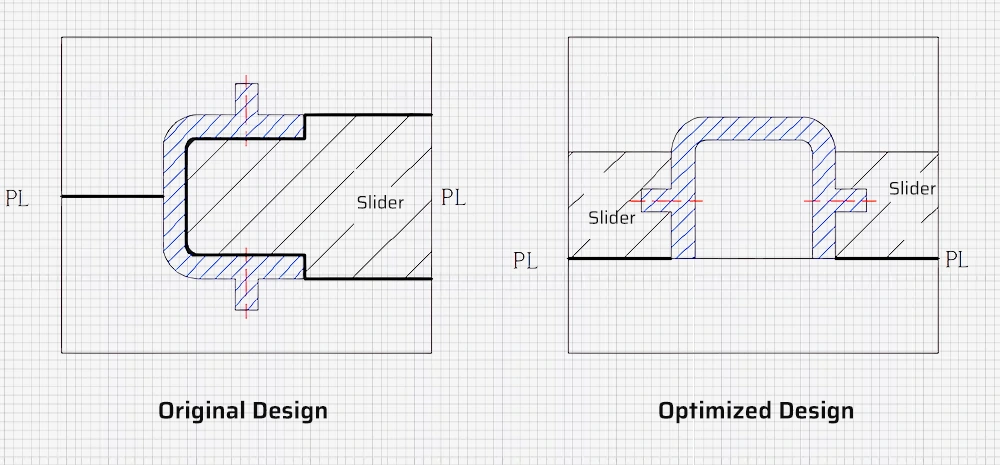
During Design for Manufacturability (DFM) review, engineers refine the AI-proposed parting line through collaborative analysis with clients. Key considerations include minimizing visible seams on aesthetic surfaces, aligning with ejector pin placement to avoid part distortion, and ensuring adequate draft (typically ≥1° per side) to prevent drag marks. Complex geometries may require stepped parting lines or shut-offs, which are validated via mold-fill simulation to eliminate air traps. The table below summarizes critical phase-specific actions:
| Phase | Key Parting Line Considerations | Technical Impact |
|—————-|———————————————————-|—————————————————|
| AI Quote | Automated draft analysis; Undercut detection | Reduces quoting time by 40%; Flags 95% of high-risk designs |
| DFM | Manual validation of shut-off angles; Ejector layout sync | Eliminates 70% of potential flash issues; Optimizes cycle time |
| Production | Precision machining of parting surfaces (±0.02mm); Hardening to 52 HRC | Ensures <0.05mm mismatch; Extends mold life beyond 50k cycles |
In production, the finalized parting line geometry is machined into high-grade tool steel (e.g., NAK80 or S136) using multi-axis CNC and EDM. Critical surfaces undergo mirror polishing to Ra ≤0.05µm, minimizing micro-gaps where flash could form. During molding, real-time pressure sensors monitor clamp force distribution across the parting plane, dynamically adjusting to maintain uniform contact. Post-molding, automated vision systems inspect the seam line for deviations exceeding 0.1mm, correlating data back to DFM records for continuous process refinement. All rapid tooling molds undergo 24-hour trial runs to validate parting line integrity before client approval, ensuring first-article parts meet ISO 2768 medium tolerances.
This closed-loop methodology—where parting line strategy evolves from AI insight through DFM rigor to production validation—enables Honyo to deliver complex prototypes in 15–25 days while maintaining <0.5% defect rates. The seamless transition from virtual analysis to physical execution underscores our commitment to technical excellence in rapid injection molding.
Start Your Project
Understanding the Parting Line in Injection Molding: A Critical Factor in Precision Manufacturing
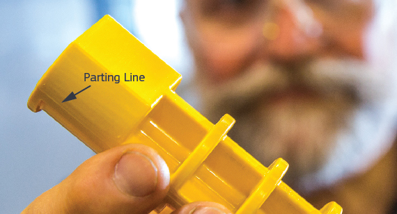
At Shenzhen Honyo Prototype, we specialize in rapid tooling and injection molding solutions that combine speed, accuracy, and repeatability. One of the most critical yet often overlooked aspects of successful injection molding is the design and placement of the parting line. This subtle but essential feature determines where the two halves of the mold meet and directly impacts part quality, appearance, and functionality.
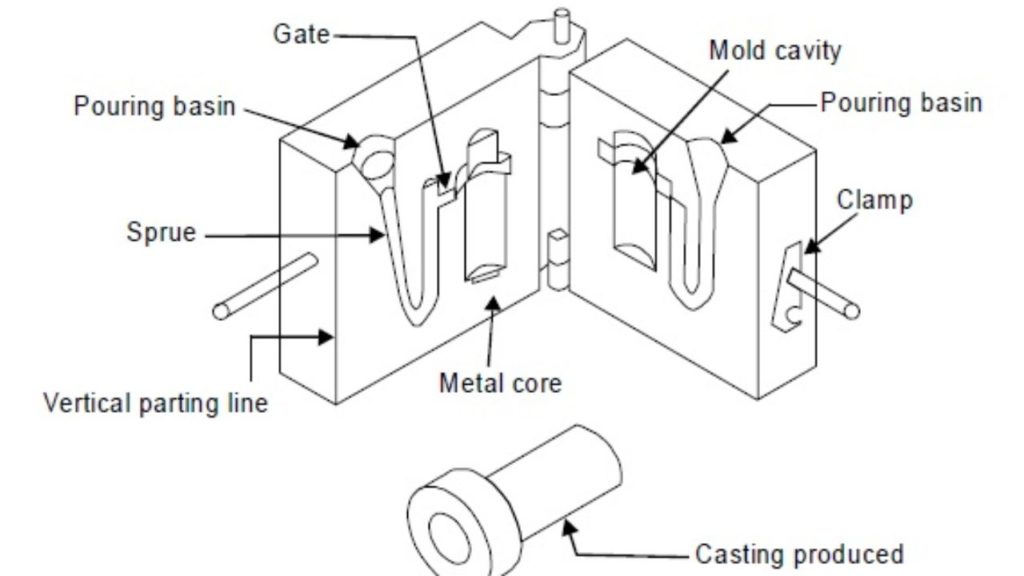
The parting line is formed where the cavity and core of the mold come together. While seemingly straightforward, improper consideration of this interface can lead to visible flash, dimensional inaccuracies, ejection issues, or cosmetic defects—especially in high-precision or consumer-facing components. At Honyo, our engineering team evaluates part geometry, material behavior, and ejection dynamics to optimize parting line placement during the tool design phase, minimizing post-processing and ensuring consistent part integrity.
Our rapid tooling process allows for quick iteration and validation, making it ideal for prototyping and low-to-mid volume production. Whether you’re developing medical devices, consumer electronics, or industrial components, early collaboration on mold design—especially parting line strategy—can prevent costly revisions down the line.
We recommend submitting your 3D CAD model early in the process so our engineers can conduct a comprehensive Design for Manufacturability (DFM) review. This includes analyzing draft angles, wall thickness, gate location, and, crucially, the optimal parting line configuration. By addressing these factors upfront, we reduce cycle times, improve surface finish consistency, and enhance overall part reliability.
Below is a summary of our standard injection molding capabilities to help guide your project planning:
| Specification | Detail |
|————–|——–|
| Material Options | ABS, PC, PP, PE, POM, PA (Nylon), PMMA, PBT, and custom blends |
| Tolerances | ±0.1 mm (standard), up to ±0.05 mm (tight-tolerance applications) |
| Tool Life | 10,000–100,000 shots (depending on steel type and part complexity) |
| Lead Time (Rapid Tooling) | 7–15 days |
| Surface Finishes | As-machined, polished (SPI standards), textured, matte, or custom |
| Secondary Operations | Assembly, heat staking, ultrasonic welding, pad printing |
Every project begins with a conversation. Our team is equipped to advise on resin selection, mold flow analysis, and parting line optimization to ensure your design translates into a manufacturable, high-quality product.
Start your project with confidence. Contact Susan Leo at info@hy-proto.com to discuss your next injection molding challenge. At Shenzhen Honyo Prototype, we don’t just build molds—we engineer success from concept to production.
🚀 Rapid Prototyping Estimator
Get a rough estimate for CNC/3D Printing costs.