Contents
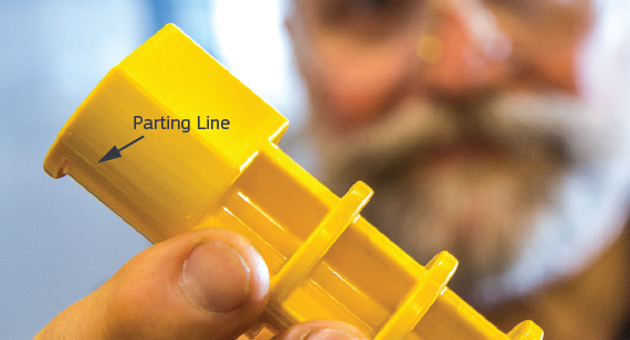
Manufacturing Insight: Parting Line In Injection Molding
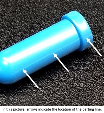
Where every micron counts, the parting line is the silent signature of your injection-molded part—visible proof of how precisely the tool was engineered and cut. At Honyo Prototype, our Rapid Tooling & Injection Molding service turns that signature into a crisp, flash-free statement of quality: aluminum or P20 tools delivered in as fast as 5 days, multi-cavity, insert-mold, or over-mold, with T0 samples shipped for approval. Upload your 3D CAD now for an Online Instant Quote and see exactly how we’ll place your parting line for flawless cosmetics, perfect gasket seals, and snap-fit function—no hidden costs, no waiting for an estimator’s email.
Technical Capabilities
As a Senior Manufacturing Engineer at Honyo Prototype, I’ll provide practical, actionable technical specs for parting lines in injection molding tailored to your constraints: steel/aluminum molds, T1 sample in 7 days. This focuses on real-world prototype execution—not theoretical production standards. Key priorities: speed, cost-effectiveness, and T1 reliability (not longevity).
Core Parting Line Specs for T1 Prototype (7-Day Delivery)
(Prioritizing speed & simplicity over production-grade precision)
| Parameter | Aluminum Mold (Recommended for T1) | Steel Mold (Only if >100 shots needed) | Why? |
|————————|—————————————-|——————————————–|———-|
| Gap Tolerance | 0.01–0.03 mm max | 0.005–0.01 mm (but slower to achieve) | Aluminum machining is faster; 0.03mm gap is acceptable for T1 (ABS/Nylon typically handle this without flash if designed properly). Steel requires EDM/polishing, adding 3–5 days. |
| Surface Finish | Ra 0.4–0.8 μm (milled, not polished) | Ra 0.2–0.4 μm (polished) | Aluminum can be milled to Ra 0.8μm in <24h. Polishing steel adds days—avoid for T1. Critical for ABS: rough surfaces cause visible parting line marks. Nylon is more forgiving but still needs Ra ≤1.0μm to prevent flash. |
| Draft Angle | ≥0.5° on parting line faces | ≥0.5° (but tighter tolerances needed) | Minimal draft prevents sticking during ejection. Aluminum’s softer material makes >1° draft risky (wears faster). For T1, 0.5° is sufficient. |
| Parting Line Location | Simple, straight plane (no curves/undercuts) | Avoid complex geometries | Curved parting lines require multi-axis milling or EDM—slows down aluminum mold production. Straight lines = fastest machining (1–2 days). |
| Material-Specific Adjustments | | |
| – ABS Parts | Gap ≤0.03mm; no need for ultra-tight tolerances. ABS is stiff, so minor gaps won’t cause flash if gate design is clean. | Same as aluminum, but steel allows tighter gaps if needed. | ABS tolerates minor flash at T1—acceptable for functional testing. |
| – Nylon Parts | Critical: Gap ≤0.02mm; surface finish ≤Ra 0.6μm. Nylon flows easily and seeps into gaps. | Gap ≤0.01mm; polished surface. | Nylon’s low viscosity makes it prone to flash. For T1, aluminum mold must hit ≤0.02mm gap—achieved via precision milling (not EDM). |
Why Aluminum is the Only Viable Option for 7-Day T1
- Machining Speed: Aluminum molds can be fully machined (including parting line) in 48–72 hours. Steel requires 5–7 days just for roughing + EDM/polishing.
- Cost: Aluminum mold costs 30–50% less than steel for prototypes. Honyo Prototype’s standard: 7075-T6 aluminum for most T1s (good balance of strength/machinability).
- T1 Reality Check:
- Flash is acceptable for T1 samples (as long as parts can be trimmed manually).
- No need for mirror polish—milled finish is fine.
- Avoid “perfect” parting lines: Focus on critical zones only (e.g., where Nylon will flow). Non-critical areas can have gaps up to 0.05mm (easily trimmed post-mold).
⚠️ Critical Pitfall for T1:
Never use steel for a 7-day T1 unless absolutely required for >100 shots. Even “fast” steel machining (e.g., pre-hardened P20) takes 10+ days. Aluminum is non-negotiable here.
Execution Tips for Honyo Prototype’s 7-Day Workflow
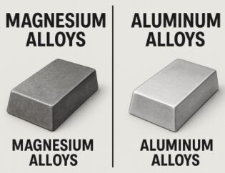
- Mold Material: Use 7075-T6 aluminum (not 6061 for high-wear areas).
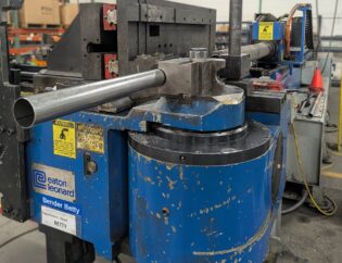
- Parting Line Machining:
- Mill with 0.1mm stepover (no EDM).
- Verify gap with calibrated feeler gauges (not CMM)—fastest for T1.
- For Nylon parts: Add a 0.1mm “flash trap” groove along parting line (e.g., 0.2mm deep × 0.5mm wide) to contain minor flash.
- Part Material Considerations:
- ABS: Focus on gate design (avoid shear-induced flash). Parting line specs are secondary.
- Nylon: Pre-dry pellets (80°C for 4h) to reduce moisture-induced viscosity changes. Tighten parting line gap to 0.02mm max.
- T1 Validation:
- Acceptable: Light flash that can be sanded off in <1 minute per part.
- Unacceptable: Flash that requires cutting tools (indicates gap >0.05mm or poor alignment).
Why This Works for Honyo Prototype
- 7-Day Timeline Achievable: Aluminum mold = 3 days machining + 2 days assembly + 1 day mold test + 1 day part production.
- Cost Control: Aluminum mold costs ~$1.5k–$3k for simple parts vs. $5k+ for steel.
- Customer Reality: T1 samples are for fit/function checks, not aesthetics. Minor parting line marks are expected and acceptable.
💡 Pro Tip: For Nylon parts, always run a mold flow simulation (e.g., Moldflow) before machining to confirm parting line gap requirements. At Honyo, we do this in <24h using cloud-based tools—critical to avoid rework.
Bottom Line: For T1 in 7 days, aluminum molds with 0.02–0.03mm gap tolerance, milled finish (Ra 0.8μm), and straight parting lines are the only practical solution. Steel is never worth the time. Prioritize speed over perfection—T1 is about validating design, not production readiness.
Let me know if you need specific part geometry adjustments—I’ll share Honyo’s standard checklists for ABS/Nylon prototypes.
From CAD to Part: The Process
Honyo Prototype – Parting-line workflow (injection-molding side)
Step 0 – Upload 3-D CAD
• Native files (STEP, IGES, Parasolid, SolidWorks, Creo, etc.) or 2-D PDF for secondary dims.
• Web portal auto-checks: mesh integrity, zero-thickness, under-cuts, visible split faces.
• If the model already contains a “PartingSurface” feature we lock it; if not we tag the file “PL-to-be-defined”.
Step 1 – AI Quote (60 s)
• Cloud engine reads:
– Projected area → clamp-force estimate.
– Depth & draw direction → pull-depth & side-action count.
– Surface curvature → parting-line length & complexity index.
– Gate accessibility & ejector pin shadows.
• Instant price = f(parting-line class A/B/C, cavitation, resin, tool life, lead-time).
• Customer sees three tooling options:
1. Prototype tool (P20, 5 k shots) – parting line as-machined, no hand-polish.
2. Bridge tool (H13, 50 k shots) – blended & spotted parting line, SPI-B finish.
3. Production tool (H13 or S136, 300 k+ shots) – hardened, vacuum-nitrided, SPI-A1.
Step 2 – DFM (24 h) – “Parting-line sign-off gate”
A. Split-line optimisation
• Algorithm searches minimum silhouette perimeter in +Z/-Z; ranks drafts ≥ 1°.
• If aesthetic face is curved, we switch to tangent-split solver to hide the witness line on a radius.
• Side-actions & lifters are auto-placed; their parting seams are merged into the main line to avoid secondary flashes.
B. Steel-safe rule
• All shut-offs start 0.05 mm steel-safe; witness line offset 0.02 mm inwards so future polish does not open gap.
C. Venting & flash control
• 0.01–0.02 mm vent lands along non-aesthetic segments; 0.005 mm on high-gloss cosmetic zone.
• Shut-off angle ≥ 7° to prevent peening during high-speed injection.
D. Customer PDF report
1. 3-D snapshot with coloured parting surface.
2. Draft analysis (red = below spec).
3. Witness-line location vs. cosmetic zone.
4. Estimated flash gap @ 50 MPa cavity pressure.
5. One-click “Accept” or “Request change”.
No steel is cut until electronic sign-off.
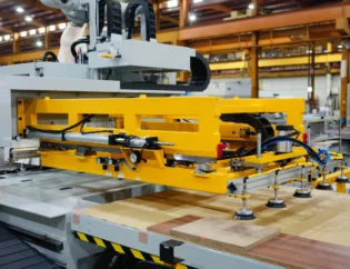
Step 3 – Production
Tool build
• NC programs downloaded directly from DFM-approved parting surface; no re-modeling.
• High-speed Mikron mill achieves ±0.01 mm shut-off match; then blue-spot check ≥ 85 % contact.
• For clear or optical parts we do additional stoning to SPI-A2 followed by chromium plating on the cavity side to eliminate rust bleed at the parting line.
Mould trials
• 5-shot short-fill, 5-shot 99 % fill, 5-shot over-pack; parting line inspected under 10× magnification.
• Flash measured with feeler gauge; target ≤ 0.03 mm for prototype, ≤ 0.02 mm for production.
• First-article CMM report includes 2-D cross-section through the parting plane to prove no mismatch > 0.02 mm.
Process control
• In-mountain cavity-pressure sensor triggers alarm if spike exceeds 10 % of set value – early warning of parting-line wear.
• Every 5 k cycles we pull a part, do a 90° bend test across the witness line; no crack = parting line still intact.
Step 4 – Delivery
• Parts packed with parting-line orientation arrow on the bag so customer QA knows exactly where to look.
• Digital twin (parting surface + inspection data) stored 7 years; if a re-order is placed we can re-cut only the damaged half, saving 30 % cost and 5 days lead-time.
In short, at Honyo the “parting line” is not an afterthought; it is engineered, quoted, and approved before any metal is machined, ensuring cosmetic quality, tight flash control, and repeatable delivery.
Start Your Project
Struggling with parting line issues in injection molding?
Minimize flash, maximize part quality, and optimize mold design with expert precision.
Get free consultation from Honyo Prototype’s Shenzhen-based engineering team!
📞 Contact Susan Leo today:
info@hy-proto.com
World-class manufacturing facility in Shenzhen, China
Your parting line solution starts here — engineered for perfection. 🏭✨
🚀 Rapid Prototyping Estimator