Contents
Manufacturing Insight: Precision Milling
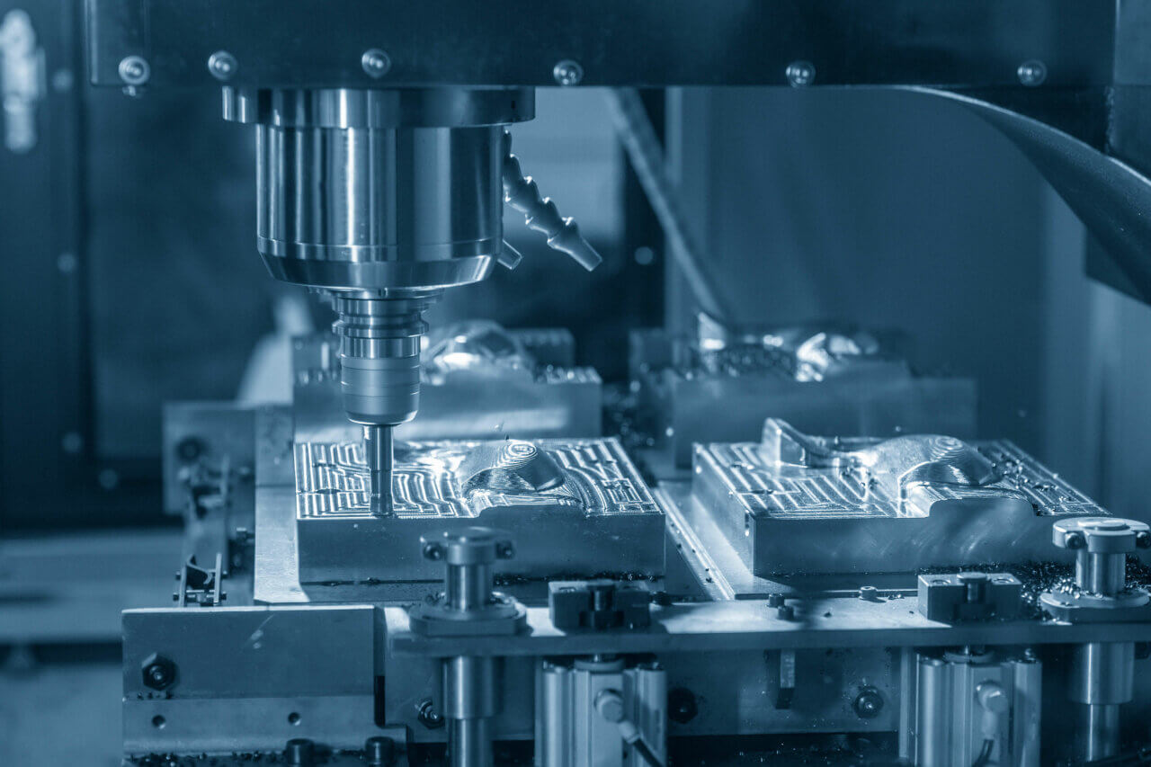
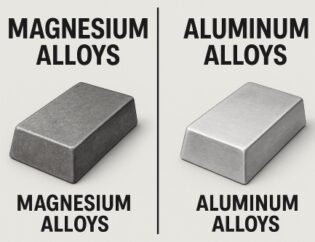
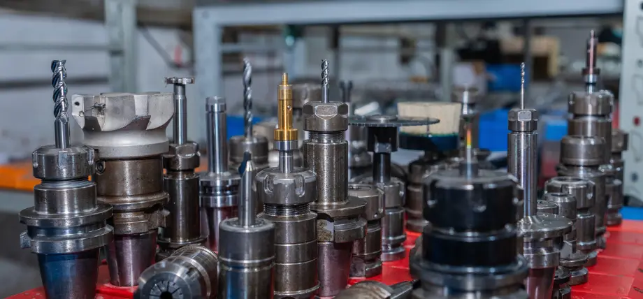
Precision milling is the art of turning micron-level tolerances into everyday reality—and at Honyo Prototype it’s what our CNC Machining division does best. From 3-axis work-holding miracles to simultaneous 5-axis contouring, we machine aluminum, titanium, engineering plastics and exotics to ±0.01 mm true position every lot, every shift. Upload your STEP or IGES file today and you’ll have an Online Instant Quote with DFM feedback in under two minutes; hit “approve” and your parts move straight to our Haas, Brother or Hermle spindles—no queues, no surprises, just aerospace-grade precision delivered in as fast as 24 hours.
Technical Capabilities
Precision Milling Technical Specifications
Honyo Prototype | Senior Manufacturing Engineer
As a precision manufacturing specialist, I define “precision milling” as the ability to consistently produce complex geometries with tight dimensional control, superior surface finishes, and repeatability across diverse materials. Below are our validated technical specs for 3/4/5-axis milling, turning, and tight-tolerance capabilities. All specs are achievable under controlled conditions (20°C ±1°C environment, calibrated tooling, and validated fixturing). Actual results depend on part geometry, material, and process optimization.
1. Axis Capabilities & Geometry Constraints
| Axis Type | Max Part Size (X/Y/Z) | Key Capabilities | Typical Applications |
|———–|————————|——————|———————-|
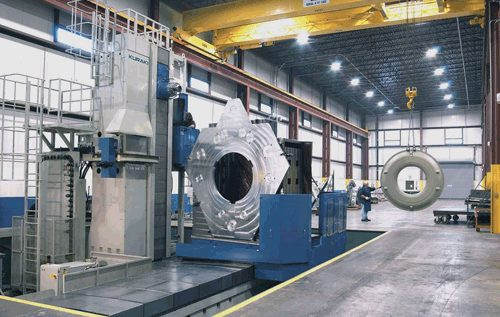
| 3-Axis | 1,200 × 800 × 600 mm | High-speed roughing, flat surfaces, simple contours. Ideal for molds, fixtures, and structural components. | Flat panels, simple brackets, housings. |
| 4-Axis | 1,000 × 700 × 500 mm | Rotation around X-axis (A-axis). Enables machining of cylindrical features, pockets on multiple sides, and complex 3D contours without re-fixturing. | Rotational parts (e.g., valve bodies), aerospace brackets with angled features. |
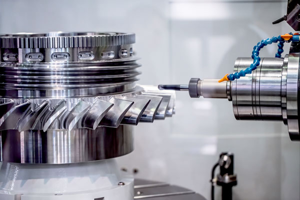
| 5-Axis | 800 × 600 × 400 mm | Simultaneous rotation around X (A) and Y (B) axes. Enables true 5-axis contouring, complex freeform surfaces, undercuts, and single-setup full machining. Minimizes fixturing errors. | Turbine blades, medical implants, aerospace structural components, intricate prototypes. |
Critical Note: 5-axis capability reduces setup errors by 90% vs. 3+2-axis positioning but requires advanced programming (e.g., CAM with dynamic toolpath optimization). We use HEIDENHAIN TNC 640 controls for seamless 5-axis motion.
2. Tight Tolerance Performance
Measured per ASME Y14.5-2018 standards. Tolerances below are achievable per part feature (not total part size) under optimized conditions:
| Material | Dimensional Tolerance | Form Tolerance | Surface Finish (Ra) | Key Considerations |
|———-|————————|—————-|———————|——————-|
| Aluminum (6061, 7075) | ±0.001″ (±0.025 mm) standard
±0.0005″ (±0.013 mm) premium | Flatness: 0.0005″/in
Straightness: 0.0003″/in | 8–16 μin (0.2–0.4 μm) | Thermal stability critical. Use cryogenic cooling for tight tolerances. |
| Steel (17-4PH, 4140, 304SS) | ±0.001″ standard
±0.0005″ premium | Roundness: 0.0002″ per inch | 8–16 μin (0.2–0.4 μm) | Requires stress-relief annealing pre-machining. Hardened steels (HRC 40+) need diamond tooling. |
| ABS (Acetal, Polycarbonate) | ±0.002″ (±0.05 mm) standard
±0.001″ (±0.025 mm) premium | Warpage: <0.001″ per inch | 16–32 μin (0.4–0.8 μm) | Moisture control is critical: Dry at 180°F for 2+ hours pre-machining. Low cutting speeds (500–1,000 SFM) to prevent melting. |
| Nylon (6/6, 6/12) | ±0.003″ (±0.075 mm) standard
±0.0015″ (±0.038 mm) premium | Warpage: <0.002″ per inch | 32–64 μin (0.8–1.6 μm) | Highly hygroscopic. Must be dried (230°F for 4+ hours). Use sharp carbide tools with high rake angles to avoid tearing. |
Tolerance Reality Check:
– “±0.0005” on steel/aluminum requires dedicated setup (e.g., vacuum chucks, thermal compensation), in-process gaging, and CMM verification.
– Plastics (ABS/Nylon) inherently have higher variability due to thermal expansion and moisture. We specify ±0.001″ only for critical features (e.g., bearing interfaces), not entire parts.
3. Turning Capabilities (Integrated with Mill-Turn Machines)
- Max Turning Diameter: 8″ (200 mm)
- Tolerance:
- Roundness: ±0.0002″
- Concentricity (between features): ±0.0005″
- Straightness: 0.0003″/in
- Surface Finish: 8–16 μin Ra (with diamond tooling)
- Key Process: Live tooling for milling operations during turning (e.g., cross-drilling, slotting). Critical for shafts with integrated features.
4. Critical Process Controls for Tight Tolerances
- Thermal Management: Machining in climate-controlled environment (20°C ±1°C). Parts cooled to ambient before CMM inspection.
- Fixturing: Vacuum chucks for aluminum/steel; custom soft-jaw fixturing for plastics to avoid deformation.
- Tooling:
- Carbide (PVD-coated) for metals.
- Diamond-coated or single-crystal diamond for plastics.
- Tool runout <0.0001″ (verified with laser tool presetter).
- Inspection: CMMs (Zeiss CONTURA G2) with 0.0001″ resolution. First-article inspection per customer specs.
5. When to Avoid “Ultra-Tight” Tolerances
- Plastics: Tighter than ±0.001″ on large parts (>6″) is rarely feasible due to material stability.
- Complex 5-Axis Parts: Tolerances <±0.0005″ require >40% longer cycle time and 2x inspection costs. We recommend tolerance analysis early in DFM.
- Thin Walls: <0.030″ walls in aluminum/steel may distort during machining. Allowance for stress relief or support structures is critical.
Engineer’s Note
“Precision isn’t just about the machine—it’s about process control. At Honyo Prototype, we engineer tolerances to the ‘sweet spot’ where cost, lead time, and functionality align. For example: a ±0.002″ tolerance on an ABS housing is often more reliable (and economical) than pushing to ±0.001″ due to plastic variability. Always start with DFM feedback to optimize tolerances for your application.”
Ready to validate your design? Share your CAD file and tolerance requirements—we’ll provide a DFM report within 24 hours.
© Honyo Prototype | Certified to ISO 9001:2015 | AS9100D (Aerospace)
From CAD to Part: The Process
Honyo Prototype – Precision Milling Workflow (upload-to-ship, 3–12 days)
-
Upload CAD
• Portal accepts any native or neutral format (STEP, IGES, Parasolid, SolidWorks, Creo, NX, CATIA, Fusion, Inventor).
• Geometry is auto-healed and tessellated in <30 s; customer sees instant 3-D preview and can add threaded holes, finishes, tolerances, critical datums, inspection level, assembly intent, and delivery zip. -
AI Quote (≤5 min)
• Cloud engine reads every face, pocket, deep-slot, under-cut, corner radius, wall height, floor radius, thin-wall L/t ratio, and tool-axis accessibility.
• Tool-library (2- to 5-axis, Ø0.1 mm–Ø25 mm, reach 0.2–200 mm) is matched; collision-free tool-paths are dry-run in GPU.
• Machine pool (3-axis Brother Speedio, 5-axis DMG MORI, Mikron HSM, Roeders, Yasda) is ranked by queue, spindle hours, and accuracy class (±5 µm, ±10 µm, ±25 µm).
• Material pricing is pulled from bar-stock, plate, or pre-machined blank inventory (Al 6061-T6, 7075-T6, MIC-6, 304/316L, 17-4, Ti-6Al-4V, PEEK, Ultem, etc.).
• Secondary ops (deburr, tumbling, anodize Type II/III, chem-film, passivate, bead-blast, silk-screen, lapping, heat treat) are auto-selected per finish call-out.
• Logistics cost and import duty are added; customer sees three delivery tiers (Express 3-day, Standard 5-day, Economy 10-day) with live capacity.
• One-click PO locks price, lead-time, and CPK sampling plan. -
DFM (≤4 h)
• Application engineer opens the digital twin in Siemens NX + PMI.
• Checks: tool-length/diameter ratio ≤8:1, corner radius ≥0.3×tool-Ø, L/D for deep ribs ≤15, under-cut accessibility, 5-axis collision, minimum wall 0.5 mm (Al) / 0.8 mm (steel), clamp surface ≥6 mm wide.
• Proposes split-body, add lugs, or turn-setup if needed; updates GD&T stack-up and datum sequence to achieve positional ±10 µm or profile ±5 µm.
• Customer approves or iterates in shared whiteboard; final BOM and route card released to MES. -
Production (CNC + post-process)
a. Material prep
– Cuts raw plate/bar on Amada band-saw; stamps heat-number for full lot traceability.
b. Setup & probing
– Schunk or Erowa pneumatic fixture mounted; Renishaw OMP40 probe maps blank Z-height and X-Y skew to <2 µm; compensates G54 automatically.
c. Roughing
– 12 000–30 000 rpm, 0.3–0.6 mm tooth feed, 60–70 % step-over; through-spindle coolant at 70 bar evacuates chips.
d. Semi-finish
– 20 000 rpm, 0.05 mm tooth feed, 0.2 mm axial stock left on walls/floors.
e. Finish & contour
– 5-axis simultaneous for blade, impeller, optical mold inserts; 0.2 mm ball-mill, 0.01 mm step-over, 0.005 mm scallop; achieves Ra 0.2 µm on 6061, Ra 0.4 µm on steel.
f. On-machine inspection
– Renishaw SP25 scans ±20 points per surface; color map vs. CAD; auto-offset if >50 % of tolerance band consumed.
g. Secondary ops
– Wire-EDM or sinker for sharp internal corners; insert installation, Heli-Coil, Keensert; 0.2 µm diamond turn for optical faces.
h. Surface treatment
– Anodize Type II (8–12 µm) or Type III hard-coat (25–50 µm) with sealed dye; chem-film MIL-DTL-5541; passivate ASTM A967; Ti anodize color; Teflon impregnation.
i. Final CMM & layout
– Zeiss CONTURA G2 0.8 + LSP-X5 scans full profile; prints AS9102 FAI or ISO 2768-mK report; CPK ≥1.33 on critical dims.
j. Laser engraving
– Part number, revision, heat code, serial, QR code for digital traveler. -
Delivery
• Parts ultrasonically cleaned in DI water, packed in anti-static ESD bags or VCI paper, bubble-wrap, 5-ply export carton; moisture-indicator and shock-label added.
• DHL / FedEx / UPS pre-alert with tracking; customs invoice and material cert (EN 10204 3.1/3.2) auto-generated.
• Digital twin + inspection report pushed to customer portal; feedback loop closes the AI training set for next quote.
Tolerance & capability snapshot
• Milled features: ±5 µm (5-axis Yasda), ±10 µm (3-axis Brother)
• Hole diameter: ±5 µm with ream; ±15 µm with interpolating
• True-position: ±10 µm on 1st operation datums
• Surface finish: Ra 0.2–0.8 µm as-milled; down to Ra 0.05 µm after diamond turn or lapping
That is the complete “upload-CAD → AI quote → DFM → precision milling → doorstep” chain we run every day at Honyo Prototype.
Start Your Project
Contact Susan Leo at info@hy-proto.com for precision milling services from Honyo Prototype’s Shenzhen facility.
Engineered to exacting tolerances. Delivered with reliability. Made in Shenzhen.
🚀 Rapid Prototyping Estimator