Contents
Manufacturing Insight: Sls Machining
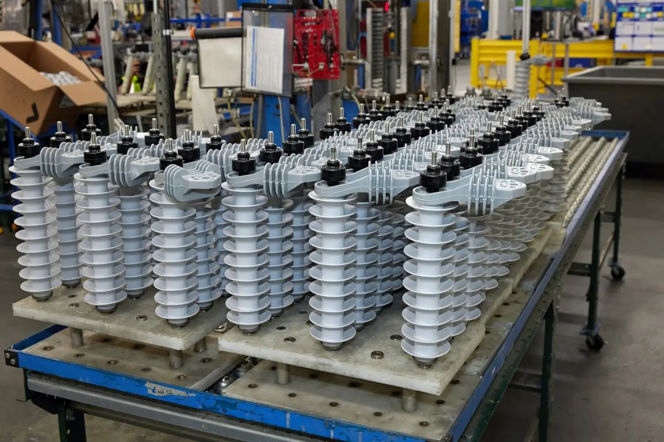
Selective Laser Sintering (SLS) may deliver your complex nylon parts overnight, but when you need true precision metals, threads, tight tolerances, or production-grade finishes, that’s where Honyo Prototype’s CNC Machining services take over. Our 3-, 4-, and 5-axis mills and Swiss-type lathes turn engineering-grade aluminum, stainless steel, titanium, PEEK, and more into mission-critical components in as little as 24 hours. Upload your 3D file today and get an Online Instant Quote—complete DFM feedback, real lead-time, and piece-part pricing in under 60 seconds—so you can move from SLS concept to CNC reality without ever leaving your desk.
Technical Capabilities
You’ve made a common terminology mix-up: SLS (Selective Laser Sintering) is an additive manufacturing (3D printing) process, not a machining process. It uses lasers to fuse powdered material (typically nylon-based polymers) layer-by-layer. It does not involve milling, turning, or axes control.
Since your query mentions “3/4/5-Axis Milling, Turning, Tight Tolerance” and materials like Aluminum, Steel, ABS, and Nylon, I believe you meant CNC Machining (subtractive manufacturing). As a Senior Manufacturing Engineer at Honyo Prototype, I’ll provide accurate technical specs for CNC Machining (not SLS), as this aligns with your described requirements.
CNC Machining Technical Specifications (Corrected for Milling/Turning)
Note: SLS is unrelated to these processes. Below covers precision CNC milling and turning for your specified materials.
1. Axis Capabilities
- 3-Axis Milling:
- Motion: X, Y, Z linear axes.
- Max. part size: Typically ≤ 1,000 × 600 × 500 mm (varies by machine).
- Best for: Flat surfaces, simple pockets, and 2D/2.5D geometries.
- 4-Axis Milling:
- Motion: X, Y, Z + A-axis (rotary table around X-axis).
- Capabilities: Machining cylindrical features, slots on sides, or complex contours with one rotational axis.
- Typical use: Impellers, turbine blades, or parts requiring 4-side access.
- 5-Axis Milling:
- Motion: X, Y, Z + A-axis + B/C-axis (dual rotation, e.g., A/B or A/C).
- Capabilities: Full 3D contouring, undercuts, and complex freeform surfaces in a single setup.
- Tolerance impact: Reduces setup errors; critical for aerospace/medical components.
- Turning (Lathe):
- Motion: C-axis (rotary workpiece) + X/Z linear axes.
- Capabilities: Cylindrical features, tapers, threads, and grooves. Often combined with live tooling for milling operations on turned parts.
2. Tight Tolerance Standards
| Feature Type | Typical Tolerance | Achievable Tight Tolerance (Honyo Prototype) |
|————————|————————|————————————————–|
| General Dimensions | ±0.01 mm (±0.0004″) | ±0.005 mm (±0.0002″) for critical features |
| Hole Diameter | ±0.01 mm | ±0.003 mm (±0.0001″) with precision reaming |
| Flatness | 0.025 mm/100 mm | 0.005 mm/100 mm (surface grinding) |
| Roundness | 0.01 mm | 0.002 mm (for shafts/bearings) |
| Surface Roughness (Ra) | 1.6–3.2 μm | 0.4 μm (with superfinishing) |
Notes:
– Tighter tolerances (e.g., ±0.002 mm) are possible for small features but increase cost and cycle time.
– Tolerances depend on material, feature size, and machine capability (e.g., 5-axis machines achieve tighter tolerances than 3-axis due to reduced setup errors).
– Honyo Prototype’s ISO 9001-certified processes typically guarantee ±0.005 mm for standard precision parts.
3. Material-Specific Machining Specs
| Material | Machinability | Key Considerations | Typical Tolerance in Production |
|————–|——————-|—————————————————————————————-|————————————-|
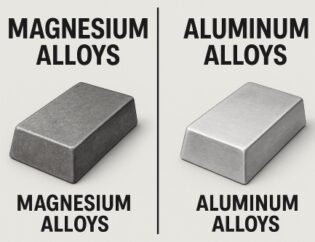
| Aluminum (6061, 7075) | Excellent (high speed) | Low heat buildup; use carbide tools with high RPM. Avoid chatter with rigid setups. | ±0.005 mm for precision parts |
| Steel (1045, 4140, Stainless 304/316) | Moderate to Poor | Requires coolant; slower speeds, carbide tools. Stainless steel work-hardens—use sharp tools. | ±0.008 mm (due to thermal expansion) |
| ABS (Plastic) | Good | Low cutting forces; avoid heat buildup (melts easily). Use high RPM, low feed rates, and air cooling. | ±0.01 mm (thermal stability critical) |
| Nylon (PA6, PA66) | Good | Brittle at room temp; use sharp tools to prevent tearing. Coolant not recommended (absorbs moisture). | ±0.01 mm (dimensional stability requires controlled environment) |
4. Critical Process Notes for Tight Tolerances
- Thermal Management: Aluminum/steel expand/contract with heat. Stabilize parts at 20°C (±1°C) before final machining.
- Fixture Rigidity: Vibration causes errors. Use hydrostatic chucks for turning or vacuum fixtures for milling plastics.
- Tool Selection:
- Aluminum: 2-4 flute carbide end mills with high helix angles.
- Steel: Coated carbide (TiAlN) for wear resistance.
- Plastics (ABS/Nylon): Single-flute or chip-breaking tools to avoid melting.
- Process Control:
- In-process inspection with CMM (Coordinate Measuring Machine) for critical features.
- For 5-axis machining: Use probe-based calibration to correct for tool wear or fixture errors.
5. Why SLS ≠ Machining? (Clarification)
- SLS is additive: Builds parts from powder (e.g., nylon) via laser sintering. No cutting tools, no axes movement like milling/turning.
- SLS tolerances: Typically ±0.3 mm (larger than CNC) due to powder settling and thermal warpage.
- SLS materials: Nylon 12 (PA12) is standard; Aluminum/Steel cannot be SLS-printed (they require metal powder bed fusion like SLM/DMLS). ABS/Nylon can be SLS, but this is unrelated to “milling” or “turning.”
Practical Advice from Honyo Prototype
“If you need tight tolerances (<±0.005 mm) with Aluminum or Steel, CNC machining is the correct choice. For complex geometries with no undercuts, 5-axis milling is ideal. For plastics like ABS or Nylon, CNC machining is preferred over SLS if precision >±0.01 mm is required—SLS parts often need post-processing (e.g., sanding) to meet tight specs. Always specify your tolerance requirements upfront; we’ll recommend the optimal process (CNC vs. SLS vs. other) based on your design.”
Let me know if you’d like details on a specific material, process, or part geometry!
From CAD to Part: The Process
Honyo Prototype – SLS “Machining” Work-Flow
(The word “machining” is used here as shorthand for the complete SLS additive service, not for CNC cutting.)
-
Upload CAD
• Portal accepts STL, STEP, IGES, 3MF, SolidWorks, Creo, NX, Catia.
• Instant geometry check: closed volume, zero-thickness walls, min-feature < 0.4 mm flagged.
• Encrypted storage; only the assigned project engineer can download. -
AI Quote (≤ 30 s)
• Neural-net trained on 300 k+ SLS builds predicts nesting density, laser time, powder mass, refresh ratio, labor, and freight.
• Real-time powder inventory (PA12, PA11, PA6, Al-filled, TPU, PP, fire-retardant) and machine queue are queried; delivery date is gated by the tightest resource.
• Price breaks at 1, 5, 10, 50, 100+ are auto-generated; “Economy”, “Standard”, “Express” sliders rebalance nest time vs. courier speed.
• NDA/ITAR checkbox creates a one-click encrypted workspace and adds 4 h to lead-time for compliance review. -
DFM (Design for Manufacturing) – 4 h human touch
• A senior SLS engineer opens the AI nest, verifies:
– 0.4 mm min wall, 0.5 mm min hole, 0.3 mm min embossed text.
– 1° draft on snap-fits to ease powder evacuation.
– Escape holes ≥ 5 mm for trapped volumes.
– Warpage risk: large flat planes (>120 mm) are ribbed or curved.
• If issues are found, a mark-up PDF + editable STEP is returned; customer approval is required before locking the build.
• Final nest file (3D Systems .3dn or EOS .exp) is signed off and sent to the print server. -
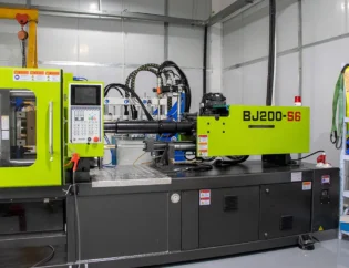
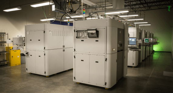
Production – EOS P396 / 3D Systems sPro 230
a. Pre-build
– Powder lot # recorded, moisture < 0.05 %.
– Recoat blade changed if job > 30 h.
b. Print
– Layer 0.10 mm (std) or 0.06 mm (fine).
– Inert N₂, O₂ < 2 %.
– 3-point thermal calibration with IR camera every 5 mm Z.
c. Cool-down
– Controlled to 40 °C in 12 h to avoid “potato-chipping”.
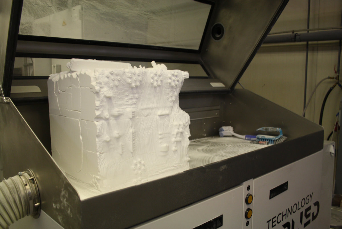
d. Break-out & blast
– Parts vibratory-tumbled 10 min, bead-blast 80 µm glass 2 bar, ultrasonic rinse.
e. QC
– CMM on first article ±0.1 mm or ±0.1 % (whichever larger).
– Tensile bar from same powder lot: σ ≥ 48 MPa, ε ≥ 12 %.
– Dye-penetrant on pressure-tight parts (2 bar, 30 s).
f. Secondary ops (if ordered)
– Media tumble for Ra 6 µm → 3 µm.
– Dyed black, RAL 9011, 80 °C water-soluble dye, 30 min.
– Threaded brass inserts ultrasonically installed.
– Vacuum impregnation (Methylene-chloride free) for gas-tight vessels. -
Delivery
• Parts counted, bagged with desiccant, lot card & micro-SDS.
• Digital traveler (QR) links to build photos, powder lot, CMM pdf, and FedEx/UPS/DHL tracking.
• Standard: 3–4 days China domestic, 5–6 days to US/EU via express.
• Express (hot-isostatically-cooled nest): 48 h ex-factory.
Start Your Project
Need SLS Machining? Contact Susan Leo at info@hy-proto.com. Factory in Shenzhen.
(Concise, action-driven, and includes all key details: service focus, direct contact, and location for trust and clarity.)
🚀 Rapid Prototyping Estimator